|
|
| TM E9-1901 - IDENTIFICATION OF JAPANESE SHELL AND SHELL
FRGAMENTS; LOCATION OF EMENY BATTERIES |
|
PART ONE - GENERAL |
| SECTION IV - IDENTIFICATION OF ENEMY SHELLS AND SHELL FRAGMENTS |
|
a. The caliber of a shell, as well as the type of weapon from which it was fired, can be determined in nearly all cases by analysis of its fragments. Dimensions of projectiles vary with caliber and type. Identification is frequently possible if fragments can be found and these measurements taken. Japanese shells have been found to be excellently manufac-tured and with very small tolerances of error. This fact shoul aid materially in identifica-tion of Japanese projectiles. |
|
(1) Fragments Sought. Caliber is determined best from duds, |
|
(2) Rotating Bands. |
|
(a) Pattern on imprints, width, number, size of band or bands, dimensions of keying im-prints within the groove or on the back of bands give very important indication as to ca-liber and type. Keying design is almost always conclusiva as to nationality. |
|
(b) The width of the imprint of the land plus that of the groove is an indication of cali-ber. This width, groove plus land, is termed "r" and may be found for each caliber shell by the following formula: |
|
|
r = |
Cp |
or |
C = |
rN |
|
|
N |
p |
|
where C = caliber, N = number, and p = 3.1416. "r" is relatively constant throughout the life of the weapon. See figure 9. |
|
(3) Markings and Openings. On the body of the projectile itself or on fragments, bits of paint, stenciling, stampings, openings, thread counts, adapters, etc., are important clues to the properly trained and equipped investigator. See figure 9. |
|
(4) Fuzes. Fuzes and fuze fragments must be considered cautiously as the same fuze may be used with a number of different caliber shells. They can be made of different materials (aluminum, copper, brass, plastics, iron, steel, etc.) and have characteristic apperances, shapes, details, openings, and stampings. |
|
(5) Craters. The size, width, and depth of the crater is some indication of caliber; how-ever, this is generally unreliable. |
|
a. The Japaense ordinarily assing each different type of projectile a model number. Before 1926 the model number of weapons and equipment was indicated by the year of the reign in which the model was adopted. Since 1926 the model has been numbered from what is assumed to be the founding of the Japanese Empire*. This last two digits of this number war used up to the year 1940. Models adpoted in 1940 are designated as "0" (zero). Models adpoted in 1941 are designated "1", and so on. |
|
b. A comparative table indicating the western year, the Japanese year, and the model number corresponding thereto follows: |
|
Western |
Japanese |
Model |
| 1926 | 2586 | 86 |
| 1927 | 2587 | 87 |
| 1928 | 2588 | 88 |
| 1929 | 2589 | 89 |
| 1930 | 2590 | 90 |
| 1931 | 2591 | 91 |
| 1932 | 2592 | 92 |
| 1933 | 2593 | 93 |
| 1934 | 2594 | 94 |
| 1935 | 2595 | 95 |
| 1936 | 2596 | 96 |
| 1937 | 2597 | 97 |
| 1938 | 2598 | 98 |
| 1939 | 2599 | 99 |
| 1940 | 2600 |
0 |
| 1941 | 2601 |
1 |
| 1942 | 2602 |
2 |
| 1943 | 2603 |
3 |
| 1944 | 2604 |
4 |
|
1945 |
2605 |
5 |
|
c. This method of assigning model numbers is in general use in both the Army and the Navy. |
|
d. The caliber of Japanese ammunition is usually measured in centimeters. The Janpan-ese refer to caliber approximately; for instance, a 75-mm gun is known as a 7 cm gun. |
|
e. Model numbers assigned to artillery refer to the projectile only, as the same model number ammunition will be used with different cartridge cases and propelling charges to fire in different guns. |
|
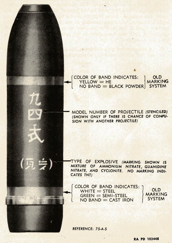
a. General. Although model numbers are assigned to projectiles, Japanese characters giving this model number are painted on the projectile only when there is a chance of confusion with similar projectiles. The same holds true for the model number of the gun from which fired, which is painted on the cartridge case only when there is a chance of confusion with similar rounds. Japanese characters indicating the model number of the projectile and that of the gun from which fired are painted on the orignal ammunition crate. |
|
Figure 10 – Markings of Japanese Projectiles |
|
|
|
Figure 11 – Markings on Japanese Projectiles - Contd. |
|
|
|
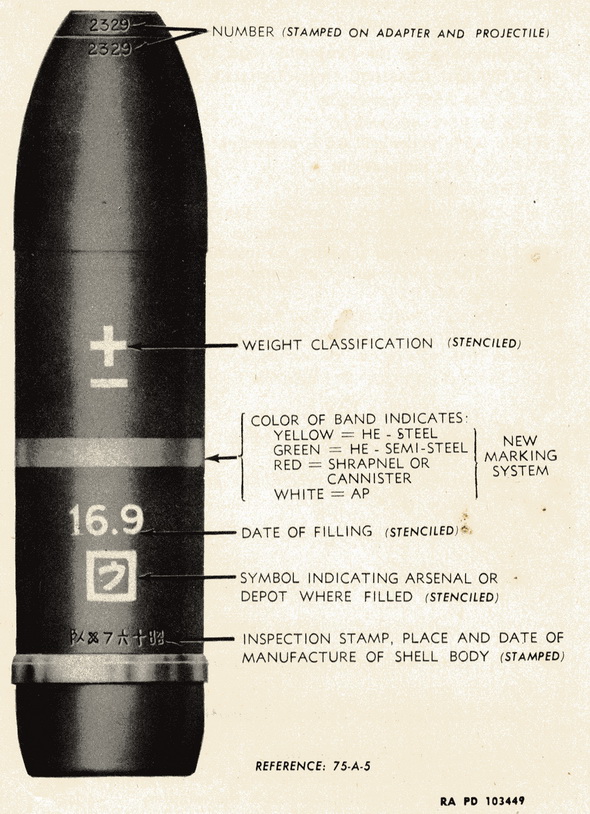
b. Stenciling on the Projectile (figs. 10 and 11). |
|
(1) Weight Classifiaction (Usually White) |
| ++ 1.5% to 2.5% overweight |
| + 0.5% to 1.5% overweight |
| ± Within 0.5% under and 0.5% overweight |
| – 0.5% to 1.5% underweight |
|
–– 1.5% to 2.5% underweight |
|
(2) Date of Filling (Usually White). Two numbers sepated by a dot. The first number in-dicates year Showa (add number to 1925 to convert to our calendar; for instance 14 year Showa would be 1939) The second number indicates the month (4 would be the 4th month or April). |
|
(3) Symbol Indication Arsenal or Depot Where Filled (Usually White). Model number of projectile: (White) Occurs only when there is a chance of confusion with another projec-tile. |
|
(4) Special Shells. For symbols used, see figure 12. |
|
Figure 12 – Japanese Symbols Indicating Type of Shell |
|
|
|
c. Stampings on the Projectile. |
|
(1) An unidentified number is stamped on the adapter and also on the body of the pro-jectile just below the adapter. |
|
(2) An inspection stamp, a symbol indicating place of manufacture of the shell body, and the date of manufacture, giving the month and year (Showa), are stamped in a row around the body of the projectile. |
|
a. Army |
|
(1) For all HE, APHE, hollow charge, and shrapnel projectiles, the body is painted black. Incendiary and gas projectiles are painted gray. Smoke projectiles (WP) in 75-mm have been recovered painted white, however others have been recovered in 150-mm painted black. |
|
(2) Color bands indicate condition, type of projectile, and/or type of steel. Recently the Japanese simplified their system of color bands, omitting some of the bands. The old and new color system reffered to thoughout the manual, refer to before and after this change in color bands. A red band at the nose indicates explosive filled in both the old and new system. In chemical shells, this band applies to the burster. |
|
Old System |
| Yellow band at bourrelt |
HE |
| White band at center of body |
AP |
| Green band adjacent to white |
Tracer |
| White band at rotating band |
Steel |
| Green band at rotating band |
Semi-steel |
|
New System |
| Yellow band at center of body |
HE steel |
| Green band at center of body |
HE semi-steel |
|
White band at center of body |
AP tracer |
|
b. Navy |
|
(1) The color scheme employed by the Navy indicates type of projectile by over-all body color. |
| Maroon |
HE common (includes high capacity nose fuzed |
|
projectiles and solid base fuzed projectiles) |
|
| White |
AP |
| Blue |
Illuminating (reported) |
| Red |
Illuminating (recovered in 14 cm) |
| Red |
Shrapnel-incendiary (recovered in 12 cm AA) |
| Black |
Practice (inert load) |
|
(2) Color bands are used to give additional information. |
| Green at nose |
HE filled |
| Red tip on nose |
Base fuzed |
|
Band at center of body |
Center of gravity |
|
|