|
|
| TM E9-1901 - IDENTIFICATION OF JAPANESE SHELL AND SHELL
FRGAMENTS; LOCATION OF EMENY BATTERIES |
|
PART ONE - GENERAL |
| SECTION V - READY REFERENCE IDENTIFICATION SYSTEM |
|
a. Any two shells of different caliber and type necessarily have certain differences in size and shape. Even shells of similar caliber and type may have great difference in some respect. By breaking down a shell into its significant or "critical" dimensions and charac-teristics, as shown in section VIII, and arranging these into a series of table with col-umns for individual items, as in section VI, systematic elimination or selection is possible, resulting in the correct identifiaction of a shell from a few clues from a small fragment or two. |
|
a. List of Equipment. |
|
RULE, steel, flexible, 12 inch (graduated in millimeters and inches - 3-fold ytpe). Alter-native: RULE, steel, flexible, 6 inch (graduated in millimeters, in tenths, and in inches, hundreths, and sixty-fourths). |
|
CALIPERS, firm-joint, outside, 8 inch. Alternative: CALIPERS, micrometer, outside, set. |
|
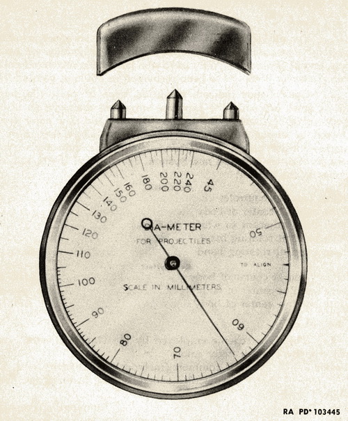
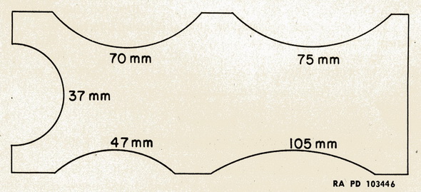
DIA-METER (fig. 13). Alternative: TEMPLATE (fig. 14). |
|
|
|
|
|
b. The Dia-Meter |
|
(1) Ordinarily, curvature or diameter of an undeformed shell fragment cannot be obtai-ned except by special means. An instrument capable of measuring diameter from frag-ments is the Dia-Meter. The Dia-Meter is made by conversion of the Geneva Lens Mea-sure. See figure 13. |
|
(2) Operation. To measure diameter, press the plunger end firmly against the shell or undeformed fragment in a plane perpendicular to the actual or estimated vertical axis. Oscillate the instrument in the hand slightly and take the least reading, which will be the diameter. The shell or fragment should be smooth and free from dirt, and an average of several readings should be used. |
|
c. Template |
|
(1) A simple template can be made in the field for the measurement of diameter of ar-tillery shell fragments. It can be made from aluminum or other metal stock, stamped and milled to the desired segment diameters in millimeters by local ordnance facilities. It is illustrated in figure 14. |
|
(2) Use. This device can differentiate between shells of fairly widely differing calibers, but is considerably less accurate than the Dia-Meter. However, its simplicity of construc-tion and its ready procurement are difnite advantages. |
|
a. Ready Reference Section, Part Two, consists of tables, drawings, and shell descript-ions. Tables are of critical shell characteristics and other identifying information arranged alphabetically by subject. The most significant characteristic in each table is listed in the first column following the nomenclature (translated Japanese designation). A combination of the first three columns in each table gives the number of the drawing which illustrates any particular shell. |
|
b. Drawings of shells are arranged by caliber and type. The type of shell is indicated by letters as follows: |
|
Letter |
Type of shell |
| A |
HE |
| B |
AP (including APHE) |
| C |
Hollow charge |
| D |
Shrapnel |
| E |
Incendiary |
| F |
Smoke |
| M |
Mortar |
|
R |
Rocket |
|
c. Different modifications of the same caliber and type are indicated by arabic numbers, thus the drawing of the first 70-mm HE shell is marked 70-A-1. A second HE shell in this caliber would be marked 70-A-2, etc. Each drawing shows enough of the exterior of the shell to give all of the known markings in addition to a cuteway view giving critical di-mensions. All measurements are given in inches. Also listed, when known, are weapons and fuzes commonly used with each shell. |
|
a. To identify a shell or shell fragment, turn to tabe giving dteails of any critical chara-cteristics noted or dimension measured. Scanning appropriate columns and by reference to other tables, possibilities may be eliminated. Reference then may be made to drawings by noting page numbers in the first three columns in each table. |
|
(1) Example 1: |
|
A shell fragment, including most of the base, has been recovered. Critical dimensions have been determined as follows: |
|
|
Inches |
| Diameter of base |
2.62 |
| Wall thickness at center of base |
.83 |
| Width of the one rotating band seat |
.40 |
|
Wall thickness at lower edge of rotating band |
.50 |
|
To use the tables for the above shell identification, proceed as follows: |
|
(a) From the list of tables in the table of contents, you find that "Diameter" is on page 34. Turn to page 34, follow dwon the column headed "Base" until you come to 2.62. You see that two projectiles have a base diameter of 2.62 inches; 7 cm Model 94 HE and 7 cm Model 97 HE Semi-steel. |
|
(b) Next from the list of tables you find that "Wall Thickness" is on page 45. Turn to page 45. Follow down column headed "Center of Base" until you come to .83. This elimi-nates the projectile 7 cm Model 97 HE Semi-steel, and you are referred to page 75-A-5 for a drawing of the remaining projectile, 7 cm Model 94 HE. From this drawing you can see that the other two dimensions closely agree. The fragment thus is identified as from a 7 cm Model 94 HE projectile and weapons employing this projectile are listed. |
|
(2) Example 2: |
|
Another shell fragment has been recovered. This fragment has been distorted by the burst so the measurements are not too accurate. Approximate dimensions have been de-termined as follows: |
|
|
Inches |
| Two rotating band seats-width of each |
.42 |
| Distance between rotating bands seats |
.25 |
| Length from band to bourrelet |
2.33 |
|
Surface length bourrelet to nose |
4.05 |
|
(a) Using the list of tables as described above, turn to "Rotating Band and Seat", page 42, follow down the column headed "Width of Rotating Band Seat" until you come to 42. There is no projectile listed opposite .42. Knowing that the measurement of .42 is not accurate, look for those having a width of rotating band seat close to .42 and that have two bands. These are two projectiles, 7 cm Model 90 HE Pointed AA (75-A-1) and 7 cm Model 90 Pointed (75-A-2). |
|
(b) Next from the list of tables, turn to "Ogive", page 40, scan down the column headed Surface Length Bourrelet to Nose, looking for the figure 4.05. The figure 4.02 opposite 7 cm Model 90 HE Pointed AA (75-A-1) is the only one reasonably close. Turning to page 75-A-1, it is noted from the drawing that the other dimension closely agrees. Thus the fragment is identified as the 7 cm Model 90 HE Pointed AA. |
|
a. Field experience has shown that the fragment most frequently found is that of the seat just under the rotating band. Therefore, plates showing actual size of this portion of the shell only, are shown on pages 48 to 57 inclusive. If a fragment of the rotating band seat is found, first turn to these plates where it may be possible to make positive identi-fication of the shell by matching the fragment with the drawings, thus avoiding reference to other tables or drawings. Note that projectiles of different calibers often use the same type of band seat and that the drawings in this section are arranged by type of band seat, all known projectiles having the same type being grouped together. |
|
Form "A" individual |
|
|
|
|
|
|