|
|
| TM E9-1901 - IDENTIFICATION OF JAPANESE SHELL AND SHELL
FRGAMENTS; LOCATION OF EMENY BATTERIES |
|
PART ONE - GENERAL |
| SECTION III - LOCATION OF ENEMY BATTERIES AND MORTARS BY CRATER ANALYSIS |
|
a. General. |
|
(1) Batteries may be indicated or located approximately from: |
|
(a) Single back-azimuth rays plus analysis of terrain along the rays. |
|
(b) Single rays plus slopes of fall. |
|
(c) Single rays plus time reading from fuzes. |
|
(2) Enemy batteries will be more accurately located by tri-angulation (long base inter-section) from back-azimuths determined in different shelled areas. |
|
b. Single-ray Method. |
|
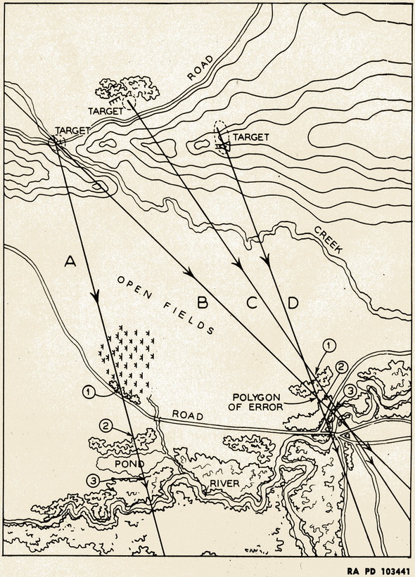
(1) By Inspection. A mean back-azimuth obtained from a group of ricochet furrows and fuze-quick craters which closely match for direction will pass near or through the respon-sible battery position. Even with no means available for ascertaining the range, the single ray will narrow the search for the enemy battery and focus the attention of all target lo-cating agencies in corps and smaller units. The capabilities and limitations of the wea-pons believed employed, as determined by identification of shell fragments, must be con-sidered. For example, on ray A of figure 6, areas (1), (2), and (3) are probable locations for enemy guns. The examination of such areas by air or ground observers, or by means of stereoscopic pairs of airplaine photographs may disclose the battery position. Possi-bility of use of unorthodox positions mut not be overlooked. |
|
(2) Slope of Fall or Time Setting Fuze. In either case, approximate ranges at times can be estimated or obtained closely from approximate range tables if caliber of weapons and type of ammunition employed are known. |
|
Figure 6 – Terrain Analysis |
|
|
|
c. Intersection Method. |
|
(1) Basically, this method is long-base intersection of mean back-azimuth rays from widely separated shelled areas, where the rays originated from craters of shells of iden-tical caliber and type, and perhaps have been further identified as having been fired from the same gun or battery, as explained in paragraph 17. The intersection of two or more, preferably at least three of these rays, is taken as the gun, battery, or battailon loca-tion. |
|
(2) Figure 7 illustrates centers of battailon areas characteristically obtained by method in step (1), above, while figure 8 shows battery location as well as battailon areas. |
|
(3) In case of a resulting small triangle or polygon of error, the center, as determined by usual means, can be taken as the loaction. In large polygons of error, the area should be inspected for probable locations as is dome in single-ray method. Referring again to figure 6, the intersection of rays B, C, and D produce a triangle of error which contains probable battery positions at (1), (2), and (3). Suspected position (2) seems most pro-bable as it is also nearest center of triangle. |
|
(4) Time factor is important; due consideration must be given to possibility that guns may have moved. |
|
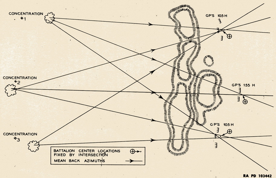
Figure 7 – Intersection Method |
 |
|
d. False Intersection. |
|
(1) When may batteries are active on a small front, the many back-azimuths tend to be dense and confusing. If all are plotted on the same map, many "false" intersections will be obtained. See figure 8. Most of these can be eliminated by simple inspection, since many false intersections will be within or near the front lines, as are (2), (3), and (7), or beyond the probable range of the two batteries as is (8). Intersections of different cali-bers, as are (1), (4), (5), and (6), are obviously false. |
|
(2) It will be noted that rays marked "A" from each concentration match up on inspect-ion being all "left" back-azimuths at each concentration; those marked "B" are each "center" and those marked "C" are "right". All A's, B's, and C's usually intersect at the same respective battery locations. |
|
(3) False intersections can be reduced by using different color rays for different caliber and type, and/or employing overlays according to caliber and type of weapon. Times of shelling should be marked along each ray. |
|
e. Accuracy. With heavy caliber guns, the accuracy of this method will be improved by the application of metro and drift corrections to the direction of flight. |
|
a. An air observer can discern the general direction of fire from a shell area, and by lin-ing in with this can greatly narrow the sector of observation. The air observer also can locate and report shelled areas for later examination by ground personnel. |
|
a. It is often possible to identify specific guns and batteries from shellresps alone. |
|
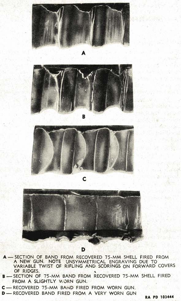
(1) Each gun leaves distinctive marks on the rotating band, as shown in figure 9, and frequently on the bourrelet of the projectile fired. These marks may permit individual identification. |
|
(2) Frequently, differences in ammunition and fuze lots will be found which may differ-entiate between battalions and sometimes batteries. |
|
(3) Slight variations in design and manufacturing peculiarities shown up very often in the rotating band keying and differentiate between ammunition lots. Keying or knurling in rotation band grooves and on the back of the bands themeselves are excellent identifi-cations of nationality, caliber, and type. |
|
(4) In crater analysis, the difference in slopes of fall, burst patterns of the projectiles, directions of flight, and settings to time fuzes will all aid in distinguishing between batte-ries or battalions. |
|
|
|
a. Counter-mortar organization and technique are covered in Training Circular No. 7, 1945, to which reference is made. |
|
b. Basically, mortar crater analysis is similar to that of artillery shell crater analysis. |
|
|