|
|
| TM E9-1901 - IDENTIFICATION OF JAPANESE SHELL AND SHELL
FRGAMENTS; LOCATION OF EMENY BATTERIES |
|
PART ONE - GENERAL |
| SECTION III - LOCATION OF ENEMY BATTERIES AND MORTARS BY CRATER ANALYSIS |
|
a. The direction of flight of a projectile frequently can be determined quite accurately from its crater or ricochet furrow. By locating the crater accurately and measuring the direction of flight as indicated in the following paragraphs, back-azimuths can be obtai-ned which will pass through of very near the actual gun, battery, or battailon position. The position area of a battery can be located by plotting the intersection of the average back-azimuths from two or more widely separated groups of craters, and by other met-hods described herein. The direction to a battery can be determined with fair accuarcy from the back-azimuth obtained from even one ricochet furrow or crater. |
|
a. By analysis of shell craters, it is possible to: |
|
(1) Verify, as active batteries, suspected locations which have been obtained by other means. |
|
(2) Detect presence and approximate location of enemy batteries not previously sus-pected. |
|
(3) Obtain an early indication of the general location or direction of the mass of enemy artillery. |
|
(4) Assist air and ground observation in accomplishing counterbattery missions by greatly reducing the sector necessary to search. |
|
(5) While a slow moving or static situation permits maximum employment and benefit of crater analysis and shellreps, crater analysis can be extremely important in a fast moving situation. For example, when adanve elements, particularly armored, are held up by un-expected fire from guns that cannot be seen, information on whether the fire is from tank, antitank, or field artillery weapons may determine the next tactical move. As very often the other counterbattery intelligence means are absent of nonoperationg at such a time, crater analysis will be frequently the only means available for speedy location and identification of these enemy guns. |
|
a. Inspection of shelled areas should be made as soon as possible. Reverse slopes, folds in the terrain, hedgerows, and buildings in shelled ereas offer the greatest chance of finding ricochet fuurows and other markings most useful in determining direction of flight and slope of fall, and also afford maximum protection for personnel making crater analysis. |
|
a. The area must be located sufficiently accurately for plotting on firing chart, map, or airphoto. Deliberate survey methods are not essential; hasty survey, by pacing distance and using the aiming circle for direction, usually is sufficient. Frequently a quick, short traverse to a known road junction, the battery position or OP, is all that is necessary. In some cases, the crater, or center of impact, can be located by pin-pricking an airphoto. |
|
a. Pattern. The pattern produced on the ground by the detonating shell gives a clear indication of the general direction from wich artillery fire is received. This is illustrated in figures 1 and 2. |
|
Figure 1 – Shell Crater With Fuze Skid |
|
|
|
Figure 2 – Shell Crater, Hard Earth |
|
|
|
b. Factors Affecting Pattern. |
|
(1) It must be kept in mind that due to irregularities of terrain and soil condition, the "typical" shell crater pattern is the exception, not the rule. |
|
(2) The principal effect from fragmentation is always from side spray, with much less effect from nose spray. Back spray is negligible. The width, angle, and density of the side spray vary with different types of projectiles. |
|
(3) In evaluating direction, due consideration must be given to the way the earth is thrown, the effect of stones, stumps, roots, variation in soil density and type, and the slope of terain at the point of impact. Out of any group only those craters most clearly defined and nearest to typical should be utilized. |
|
c. Range Dispersion. In case the firing has been from a single gun or a very limited number of guns, range dispersion will give a good indication of the direction of fire. |
|
d. Marks on Vegetation and Other Objects. The direction from which a round was fired and its angle of fall are often accurately indicated by markings left as it cuts through trees, shrubs, grass, snow, and various objects. |
|
e. Ricochet Furrows and Duds. |
|
(1) Ricochet furrows usually furnish the best information. The average direction of a fw such furrows from the same gun will give a line within a few mils of the true direction of flight. Ricochet can be found even at extreme ranges, on reverse slopes of hills or on stream banks. Of equal or superior value are grooves in thick grass or bushes, holes through materiel, buildings, trees and other objects from which angle of fall also freq-uently may be determined. |
|
(2) Techique (fig. 3). Carefully remove loose dirt from furrow with hands, leaving smooth, hard channel intact. Drive two thin stakes or survey pins, one at each end of the usable part of the furrow. Be sure to set the stakes straight and in the center of the channel. These stakes represent the line of fire, the azimuth of which may be measured with an aming circle placed 5 to 15 feet from the furrow and in line with it. The slope of fall can be determined with a Compass M2 sighted along the bottom of the furrow or entrace hole. |
|
Figure 3 – Typical Ricochet Markings |
|
|
|
f. Fuze-quick Craters. |
|
(1) At small angles of all, fuze-quick craters furnish information nearly as accurate as that from ricochet furrows. Judging the direction of the trajectory increases in difficulty with an increase in angle of impact; therefore, for equally practical results, more craters must be analyzed. If the angle of impact is small or moderate, the crater generally is pear-shaped. The crater usually is wider than it is long. If the angle of impact is larger, the crater generally is oval with the least diameter in the direction of flight. |
|
(2) Techniques (figs. 4 and 5). |
|
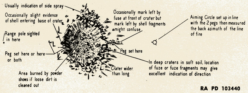
(a) Use of Channel in Ground Where Shell Entered and/or Left. Place a stake in center of channel. Place a second stake on opposite side of crater. Sight along these to obtain back-azimuth as with ricochet furrows. Position of fuze may give an excellent indication. |
|
(b) Use of Side Spray Shown by Dirt and Cut Grass. Place a stake in the center of each line of side spray equally distant from the crater. Putting the aiming circle in the exact center of the crater, measure the angle between the stakes. The bisector of this angle is the approximate line of fire, and its azimuth, or bacl-azimuth, can be determined. |
|
(c) The averarge of the back-azimuths obtained from steps (a) and (b), above, will be more accurate than either method alone. |
|
Figure 4 – Typical Shell Crater, FQ (Small Angle of Fall) |
|
|
|
Figure 5 – Typical Shell Crater, FQ (Larger Angle of Fall) |
|
|
|
g. Deep Craters. Least reliable directions are from deep craters. However, in soft soil, good approximate direction can be obtained if a nose fuze has been employed and fuze and fragments are located. These will often be found in a tunnel in prolongation of the shell's line of flight. A line can be established from this conjunction with other character-istics. The crater pattern ordinarily will be oval, narrowest diameter indicating direction of fire, and of varying depths. |
|
h. Time Fire. Low air bursts can furnish excellent information of the line of flight of the projectile. In any time concentration there should be some impact from which good di-rection lines can be obtained. |
|
|