|
|
| BRITISH EXPLOSIVE ORDNANCE |
| Part 3 - Chapter 2 |
| High-Explosive Rockets |
|
3-in. Aircraft Rocket (Service) |
| Data |
| H.E. Shells | 60 lb. F | 60 lb. S.A.P. |
|
Over-all length |
22.0 in. | 21.8 in. |
|
Diameter |
4.5 in. | 6.0 in. |
|
Total weight |
46.9 lb. | 60.0 lb. |
|
Fuzing |
No. 899 Mk I | No. 865 Mk I, or No. 878 Mk I |
|
Filling |
TNT or RDX/TNT 60/40 | TNT or Amatol 60/40 |
|
Filling weight |
3.9 lb. | 12.0 lb. |
|
Solid shot |
25 lb. A.P. and S.A.P. Mk I |
25 lb. A.P. Mk II |
|
Over-all length |
12.4 in | 14.7 in. |
|
Diameter |
3.44 in. | 3.8 in. |
|
Total weight |
25.0 lb. |
24.75 lb. |
| Rocket Motor | ||
|
Over-all length |
55.19 in. | |
|
Diameter |
3.25 in. | |
|
Width of fins |
5 in. | |
|
Total weight |
35.1 lb. | |
|
Burning time at 60° F. |
1.5 seconds | |
|
Propellant |
Mk I tubular cordite; Mks II and III cruciform cordite | |
|
Porpellant weight |
Mk I, 12.6 lb.; Mks II and III, 11.3 lb. |
|
|
General: This is a aircraft rocket weapon, designed primarily for use against subma-rines and merchant shipping, although more recently wide use of the rocket has been made against land targets of an unarmored or lightly armored nature. The round consists of a 3-in. aircraft rocket, motor and one of the five following heads: Shell, H.E., 60-lb., F., No. 1 Mk I; Shell, H.E., 60-lb., S.A.P., No. 1 Mk I (with delay); Shell, H.E., 60-lb., S.A.P., No. 2 Mk I (wihtout delay); Shot, 25-lb., S.A.P., Mk I; Shot, 25-lb., A.P., Mk I; and Shot, 25-lb., A.P., Mk II. In addition, two concrete practice heads are also used, one weighing 25 lb, the other 60 lb. |
|
Description |
|
Shell, H.E., 60-lb., F., No. 1 Mk I – This shell has been manufactured by modifying a 4.5-inch Howitzer shell. The nose of the shell is recessed and internally threaded to re-ceive the nose fuze, while the base portion carries a threaded spigot for attachment to the shell ring of the rocket motor. The shell is painted dark green over-all, with the de-signation stencilled in ½-in. yellow letters around the shell body. |
|
Shell, H.E., 60-lb., S.A.P., Nos. 1 and 2 Mk I – This shell consists of a cylindrical steel body internally threaded to receive a heavy steel ogival nose cap. The after portion of the body is internally threaded to receive a spigot, by which the shell is attached to the shell ring of the rocket motor. In the spigot are carried a gunpowder thermal initiator and a base fuze, beneath which is located a C.E. booster pellet. The shell is painted green over-all, with a ½-in. white and a ½-in. red band near the nose. A 1-in. light green band is painted around the shell body, and on this band are stencilled the initials of the explo-sive main filling. |
|
The Head No. 1 Mk I employs the Fuze No. 865 Mk I (with delay) and the No. 2 Mk I uses the Fuze No. 878 Mk I (without delay). This is the only difference in the two shells. |
|
Shot, 25-lb., S.A.P., Mk I – This is a solid steel shot. The nose portion of the shot is ogival, while the after portion terminates in a threaded spigot of reduced diameter, which screws into the shell ring of the rocket motor. The shot is painted black over-all, except for the nose end, which is painted white for a distance of one inch. |
|
Shot, 25-lb., A.P., Mk I – Externally this shot appears identical to the S.A.P. shot. The nose portion is ogival, and the after body consists of a threaded spigot of reduced dia-meter, which screws into the shell ring of the motor. This spigot, in the case of the A.P. shot, is a separate component screwing into the internally threaded base portion of the shot. The spigot is held in place by a locking pin or a set-screw, which pierces the spigot and engages the shell body. The shot is painted black over-all, but carries a ½-in. white band in addition to the 1-in. white tip on the nose. |
|
Shell, 25-lb., A.P., Mk II – This shot consists of a solid steel body machined externally to form a double ogive. This contour is considered to result in greater penetration and better underwater ballistics. Penetration is also enhanced by heat-treating the body of the shot. The after end of the body is recessed to form an empty cavity, and the base of this cavity is closed by a threaded spigot which screws into the shell ring of the ro-cket motor. The shot is painted black over-all, with a 1-in. white tip, and a ½-in. white band on the nose. |
|
Shot, 60-lb., Practice (Concrete), Mk I – This is a blunt-nosed cylindrical head consis-ting of an adapter, externally threaded to screw into the shell ring of the motor and fit-ted with eight steel reinforced rods, welded into place. The concrete is the formed around the reinforced rods and shaped to measure 20 inches over-all and 6 inches in dia-meter. |
|
Shell, 25-lb., Practice (Concrete), Mk I – This shell is manufactured in an identical manner to the 60-lb. Practice Shell, but measures only 11.5 inches in length and 5 inches in diameter. |
|
Motor, Rocket, A/C, 3-in. No. 1 Mk I – This motor conists of a long steel cylinder with a shell ring at the forward end held in place by eight locking pins, which are held in en-gagement by two circular band spring. A thin metal-headed obtruator is located beneath the shell ring and is separated by cardboard washers from the forward end of the propel-lant grain. The head of the grain is castellated to accommodate the Igniter, Fuze, Elec-tric, No. 53*. The base of the propellant grain is supported by a metal grid, which in turn rests against the tail obtruator. The steel venturi tube is welded to the inside of the mo-tor just behind the tail obtruator and contains a bag of silica gel as a moisture-proofing measure. |
|
The igniter leads extend from the igniter through the central annulus of the tubular cordite grain, along the outside groove of the cruciform grain in the Motors No. 1 Mks II and III. through the tail obruator and venturi, and through the metal closing plate, and terminates in a two-pronged plug. This plug connects with a socket extension on the rail launcher, when the rocket is loaded aboard the plaine. |
|
Eight slots are located in the motor body near the after end for attachment of the four fins. The rocket are suspended by two saddles, each carrying a T-lug, which rides in the grooves of the launcher rails. |
|
Motor, Rocket, A/C, 3-in., No. 1 Mk II – This motor differs from the No. 1 Mk I in that the propellant grain is cruciform in shape rather than tubular. The igniter leads are brought along the outside grooves of the grain, rather than through a central annulus, and a different type grid is employed. Proposed new nomenclature for the Motor No. 1 Mk II is: Motor, Rocket, A/C, 3-in., No. 5 Mk I. |
|
Motor, Rocket, A/C, 3-in. No. 1 Mk III – The main difference between, the Motors Mk II and Mk III is that the Mk III has a weak link pigtail as against a niphon plug in the Mk II motor. The proposed new nomenclature for this motor is Motor, Rocket, A/C, 3-in., No. 5 Mk II. |
|
Motor, Rocket, A/C, 3-in., No. 1 Mk IV – This motor differs from the No. 1 Mk III in that a small metal clip is loosely inserted over the igniter leads between the niphon plug and the attachment to the metal closing disc. The Motor Mk IV also has a longer pigtail lead; this greater length of lead being required for the lower round when using the "tier carriage" scheme. The proposed new nomenclature for this motor is Motor, Rocket, A/C, 3-in., No. 5 Mk II. |
|
Remarks: These motors are colored either green ot white over-all, which identifica-tion stencillings in yellow. |
 |
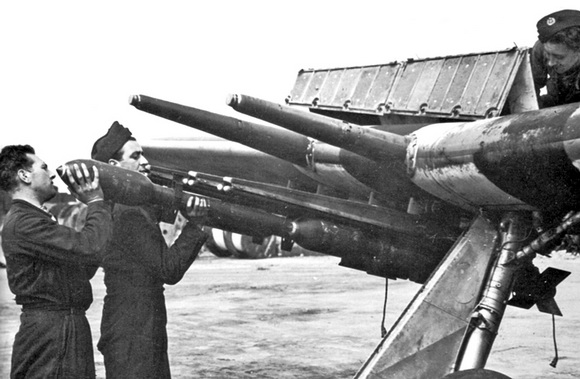
| Figure 190 – Assembled 3-in. Aircraft Rocket |
 |
| Figure 191 – 3-in. Aircraft Rocket Components |
 |
| Figure 192 – 3-in. Aircraft Rocket Components |
 |
 |
|
|