|
|
| BRITISH EXPLOSIVE ORDNANCE |
| Part 3 - Chapter 2 |
| High-Explosive Rockets |
|
3-in. Barrage Rocket, "Land Mattress" (Service) |
| Data |
| H.E. Shell | ||
|
Over-all length |
14.75 in. | |
|
Diameter |
5.0 in. | |
|
Total weight |
34.25 lb. | |
|
Fuzing |
No. 721 Mks II* and III, and No. 725 Mk I | |
|
Filling |
Amatol 60/40 or 50/50 |
|
| Rocket Motor | ||
|
Over-all length |
55.19 in. | |
|
Diameter |
3.25 in. | |
|
Width of fins |
0.75 in. (approx.) | |
|
Total weight |
30 lb. | |
|
Propellant |
Cruciform cordite | |
|
Weight of propellant |
11.5 lb. | |
|
Burning time at 60° F. |
1.5 seconds |
|
|
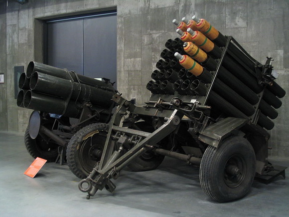
General: The Land Mattress rocket is designed as a barrage rocket for land service use. The motor employed is an adaption of a 3-in. aircraft rocket motor, the modification consisting of a cutting down the tail fins. Loss of stabilization due to the reduced tail surface is regained by imparting a spin to the rocket with spiral rails in the barrel of the launcher. |
|
Description |
|
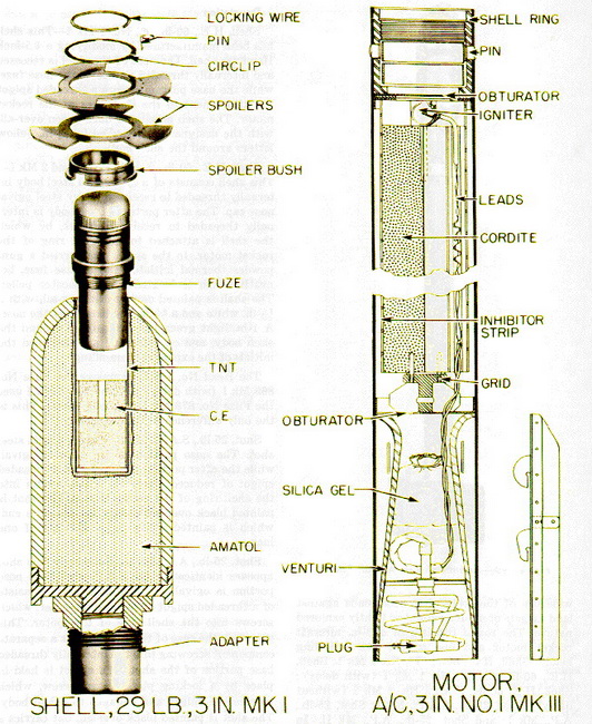
Shell, H.E., 29-lb., 3-in. Mk I – This shell is a modification of the 29-lb. H.E. shell used with the 5-in. barrage rocket. The modification consists of a threaded adapter screwed to the spigot on the base plate of the shell. The adapter is externally threaded to screw into the shell ring of the 3-inch rocket motor. Further modification of the shell includes alteration of the exploder pocket to receive the larger booster assembly of the Fuze No. 721. The shell is painted buff over-all, with a ½-in. red band painted around the nose portion of the shell and a 1-in. green band painted around the shell body. On this band the initials of the type of filling used are stencilled in black. |
|
Motor, Rocket, A/C, 3-in., No. 1 Mks III – The motor is identical to the Motor No. 1 Mk II, except that a single-pronged plug has been substituted for the two-pin plug on the end of the igniter leads. The motor, when used with the Land Mattress rocket, employs tail fins of a reduced width instead of the standard 5-in. fins. |
|
The motor must not be fired outside the temperature range of -5° to 135° F. |
|
Remarks: A novel method of varrying range is incorporated in this rocket. Two spoiler plates, which consist of metal discs with three equi-spaced, cut-out segments, are pla-ced face to face and are fitted to a spoiler bush. The spoiler bush is a collar which fits over the top of the Fuze No. 721 and is recessed so as not to foul the protruding ends of the shear wire. The bush engages with the top cannelure of the fuze and is held attach-ed to the fuze by a locking wire around the fuze body. The spoiler plates are secured to the spoiler by a spring steel circlip, which engages a groove in the bush just above the spoiler plates. Four small holes are drilled in one segment of each plate. Range variations are obtained by varrying the relative positions of the spoiler plates to give different areas of wind resistance. The setting given to the spoiler plates is maintained by passing a special locking pin through the aligned holes in the plates. |
|
These different sizes of spoiler plates may be used, the smallest of which is painted red on one side, the medium size, blue, and the largest white. |
 |
| Figure 188 – Assembled 3-in. Barrage Rocket |
 |
| Figure 189 – 3-in. Barrage Rocket Components |
 |