|
|
| BRITISH EXPLOSIVE ORDNANCE |
| Part 3 - Chapter 2 |
| High-Explosive Rockets |
|
3-in. Aircraft Rocket, Air-to-Air (Soon in Service) |
| Data |
| H.E. Shell | ||
|
Over-all length |
9.29 in. | |
|
Diameter |
3.25 in. | |
|
Total weight |
7.6 lb. | |
|
Filling |
TNT | |
|
Filling weight |
2.125 lb. | |
|
Fuzing |
No. 720 Mk IV |
|
| Rocket Motor | ||
|
Over-all length |
31 in. | |
|
Diameter |
3.25 in. | |
|
Width of fins |
0.75 in. | |
|
Total weight |
19 lb. (approx.) | |
|
Propellant |
7 grains of tubular cordite | |
|
Propellant weight |
4.2 lb. | |
|
Burning time at 40° F. |
0.3 sec |
|
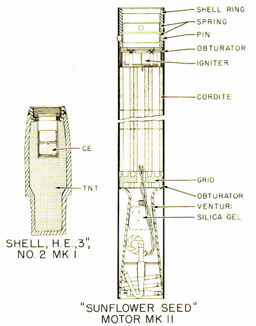
General: This rocket was designed for upward vertical firing from heavy bomber air-craft to disrupt attacking formations of enemy fighters. The rocket head is fitted with a self-destroying fuze so that misses will not fall on friendly aircraft or territory after expi-ration of the rocket motor. The round consists of a 3-in. light ogival Shell No. 2 Mk I fit-ted with a Fuze No. 720 Mk IV, and a Motor, Rocket, A/C, 3-in., Mks I and II "Sunflower Seed". |
|
Description |
|
Shell, H.E., 3-in., No. 2 Mk I – This shell was originally designed for use with the 3-in. antiaircraft rocket and the Fuze No. 701, but has been slightly modified for use with this rocket weapon. The shell consists of a light steel ogive strucks with a 30-inch radius. The after part of the shell body is reduced in diameter and is threaded externally to screw into the shell ring of the rocket motor. An internally threaded fuze adapter is wel-ded into the forward end of the shell body. A cardboard exploder container is inserted into the main explosive filling beneath the fuze adapter and contains two 12-dram C.E. booster pellets. |
|
The shell is painted buff over-all and carries a stencilled ring of red crosses ½-in. wide and one inch below the forward end of the shell body. A green band, upon wiche are stencilled the black letters TNT, is located 4.5 in. below the forward end of the shell. Complete identication, filling, and manufacturing information is stencilled in black on the shell body between these two rings. |
|
Motor, Rocket, A/C, 3-in., Mks I and II "Sunflower Seed" – The rocket motor is a standard 3-in. proof reduced in length to 31 in. by elimination of a cardboard spacer sleeve. The motor consists of a cylindrical steel body, fitted at the head end with a shell ring, which is held in place by eight spring-locked pins. A head obturator is located be-hind the shell ring. The propellant consists of seven tubular grains of flashless cordite, each grain measuring 1 in. in diameter by 18 in. in length. The igniter leads pass from the igniter along the outside of the grains and end in a two-pronged niphon plug. A tail obtu-rator is located aft of the propellant grains, and a venturi is located in the base of the motor. A small bag of silica gel is placed in the venturi as a moisture-proofing measure. |
 |
| Figure 193 – 3-in. Aircraft Rocket (Air-to-Air) Components |