|
|
| DEPTH CHARGES MARK 6 and MARK 7 |
| PART II |
| CHAPTER VI - REPAIRING AND OVERHAULING |
|
REASSEMBLY OF THE PISTOL |
 |
13. To reassemble the pistol do this: |
|
(a) Coat all metal parts with Polar Type Rust Preventive Compound (52-C-18) Grade II. This compound may be applied by dipping or spraying. Allow the parts to drain. |
|
|
(b) Clean the inside of the mechanism casing and guide tube assembly, especially that part of the guide tube in which the bushing fits. |
|
|
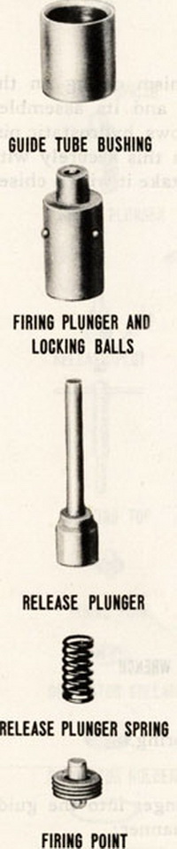
(c) Insert the bushing in the guide tube with the cham-fered end away from the centering flange. Apply a light coat of red lead to the threads on the guide tube bush-ing follower and screw it in place with the toll provided. Remove excess red lead. |
|
|
(d) REASSEMBLE THE FIRING PLUNGER as follows: |
|
|
(1) Put lock balls in place. A small amount of vase-line on each ball will keep it from falling back within the plunger bore. |
|
|
(2) Insert release plunger. Make sure that it is not burred or badly scarred. |
|
|
(3) Insert firing plunger spring and screw firing point into place. Lock the firing point by staking or with a spot of solder. |
|
|
(4) Try the release plunger by pushing it in by hand several times. |
|
|
(f) Insert the firing spring. |
|
|
(g) Put the firing plunger into the guide tube in the fol-lowing manner: |
|
|
(1) Slide the firing plunger sleeve provide in the Mark 2 Mod. 1 tool set onto the firing plunger. De-press the release plunger so that balls can recede, and slide the sleeve over the balls. |
|
|
(2) Start the firing plunger into the guide tube. As the plunger goes into the guide tube, tha balls will be held in place by the guide tube bushing. And sin-ce the sleeve cannot pass the guide tube bushing follower, the sleeve will be automatically removed when the firing plunger is pushed into the guide tube bushing with the cocking tool. Do not cock the firing plunger in backwards, be sure that the firing point is outward, toward the detonator holder. |
|
|
(h) Replace the detonator collar, detonator holder and detonator holder spring. |
|
|
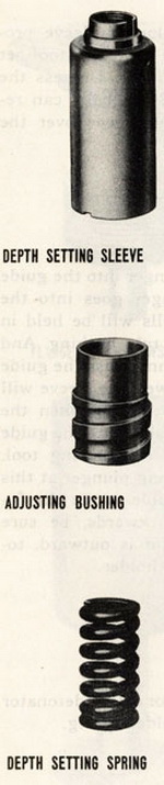
(i) Screw the adjusting bushing into the depth setting sleeve to insure that these parts fit smoothly. Make sure that there are no burrs in threads. |
|
|
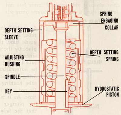
(j) Drop the adjusting bushing down over the hydrostatic piston stem and key. |
|
|
(k) Place the depth setting spring in the adjusting bush-ing and screw the spring engaging collar on the end of the hydrostatic piston stem. Lock the collar in place by staking or with a spot of solder. If solder is used remove all trace of flux. |
|
|
(l) Make up the sub-assembly consisting of the depth setting sleeve, dial plate, index pointer carrier, index pointer and inlet valve (Mark 6) or deep firing mechanism (Mark 6 Mod. 1) in the following manner: |
|
|
|
|
 |
 |
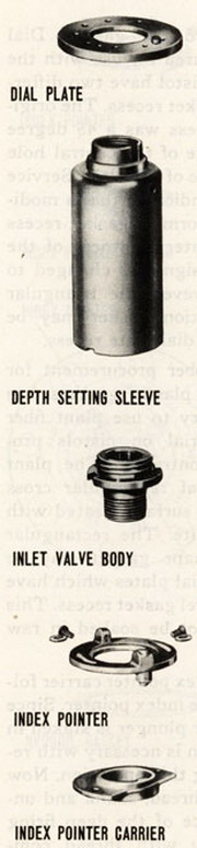 |
(1) MARK 6: – Secure depth setting sleeve upright in assembling fixture. Place dial plate on the sleeve. Then assemble index pointer carrier and with index pointer plunger assembled as noted in paragraph 6 (j) 2 and 3 put the index pointer in place. Now screw in the inlet valve. Secure index pointer to carrier with round head brass screws with washer under screw leads. Locate the index pointer with respect to the carrier so that these screws are located at approximately the center of the acurate slots in the index pointer. Before tighte-ning the inlet valve securely, rotate the dial plate so that the dial plate lock pin hole is in line with the index pointer "V" and 180 degrees from it. |
|
(2) MARK 6 MOD. 1: Secure depth setting sleeve up-right in assembling fixture. Place tirangular shaped cross section gasket on neck of sleeve with base of gasket uppermost. Material procurement difficulties have made it necessary to use two types of gasket. The triangular shaped, cross-section gasket made of a plastic material is composed of asbestos fiber impreg-nated with graphite and binder which includes some rubber. This gasket should be soaked in raw caster oil for one hour before it is installed on the depth setting sleeve. |
|
|
Put the dial plate on the neck of the depth setting sleeve with gasket recess side toward the gasket. Dial plates ma-nufactured for use with the Mark 6 Mod. 1 pistol have two different shapes of gasket recess. The original shape of re-cess was a 45 degree bevel on the edge of the central hole at the bottom face of the plate. Service tests of pistols in-dicated that a modified "V" shape form of gasket recess im-proved the water tightness of the pistol so the design was changed to this shape. However, the triangular shape cross section gasket may be used with either dial plate recess. |
|
|
Difficulty in rubber procurement for manufacture of plastic gaskets has made it necessary to use plant fiber as gasket material on pistols produced by one contractor. The plant fiber gasket is of rectangular cross section and it is surface treated with powdered graphite. The rectangular cross sec-tion shape gasket may be used only with dial plates which have the 45 degree bevel gasket recess. This gasket should not be soaked in raw castor oil. |
|
|
Assemble the index pointer carrier following it with the index pointer. Since the index pointer plunger is staked in place no attention is necessary with respect to it during this ope-ration. Now coat the screw thread, shank and under flange surface of the deep firing mechanism body with thread compound and screw this mechanism into place. |
|
|
|
Secure the index pointer to carrier with round head brass screws with appropriate type washers under screw heads. Locate the index pointer with respect to the carrier so that these screws are loacted at approximately the center of the arcuate slots in the index pointer. Before tightening the deep firing mechanism securely, rotate the dial plate that the dial plate lock pin hole is in line with the index pointer "V" and 180 degrees from it. While it is necessary to secu-rely screw the deep firing mechanism into place, excessive force should not be used because the thin wall between the external and internal screw threads on the shank may be stretched. This distortion of the body will disturb the calibration of the device. See paragraph 15 below for cali-bration of this mechanism. The sub-assembly made up in accordance with the foregoing instructions should now be tested for water-tightness of the gasket between the dial plate and the deep setting sleeve as noted in paragraph 16 below. |
|
(m) Place the .010 inch thickness hydroil gasket on its sur-face in the pistol carrying flange. A hole in this gasket fits over the dial plate lock pin which is pressed into the flange. A new dry gasket should be used. Do not use shellac on this gasket. The polar type rust preventive compound on the metal surface will aid sealing when the joint is made up. |
|
|
(n) Now place the sub-assembly noted in (1) above into the hydrostatic chamber. The depth setting sleeve will rest on the adjusting bushing with the matching acme threads of these parts at the beginning of engagement. The index pointer will be positioned in line with the 30 foot dial mark-ing. Grasp the idex pointer with the hand and turn the sub-assembly clockwise. Two complete turns will properly posi-tion the sub-assembly in the pistol with the index pointer located at 30 foot dial setting and the dial plate stop pin entered in its matching hole in the dial plate. |
|
|
|
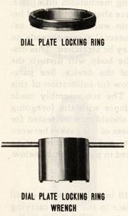
(o) Screw the dial plate lock ring into place with the wrench provided. Using a drift held against the edge of one of the wrench slots in the lock ring, seat the ring securely with a hammer. It is important that the dial plate be tight-ened securely on the .010 inch hydroil gasket to prevent leakage at this joint on the Mark 6 Mod. 1 pistol. The use of a drift will not be necessary on the Mark 6 pistol. |
|
(p) Cock the firing plunger. The pistol is now ready for cali-bration as described in paragraphs 6 and 7 above. |
|
|
(q) AFTER CALIBRATION: |
|
|
(1) Pistols returned to store should be cocked, index pointer set at "30", small pointer (Mark 6 Mod. 1) set at "500" and plain safety cap screwed on. |
|
|
(2) Pistols returned to service should be cocked. The positions of index pointer or pointers, type of safety cap fitted and attachment of detonator shall be as cir-cumstances require. |
|
|
(3) A tag should be attached to each pistol. This tag should contain such information as the name of the ac-tivity performing the overhaul, date of overhaul and name or initials of officer in charge of overhaul and test. |
|
|
|
|
|