|
|
| DEPTH CHARGES MARK 6 and MARK 7 |
| PART II |
| CHAPTER VI - REPAIRING AND OVERHAULING |
|
ASSEMBLY OF DEPTH SETTING MECHANISM - MARK 6 MOD. 1 PISTOL AND TEST FOR WATER TIGHTNESS OF PISTOL SUB-ASSEMBLY |
 |
14. All parts should be clean and free from dirt or chips. Polar type Rust Preventive Compound (52-c-18) Grade II should be applied to all metal parts prior to assembly. This treatment may be applied by either spraying or dipping. Parts should be drai-ned after treatment. |
|
15. Assemble the deep firing mechanism as fol-lows: |
|
|
(a) Screw valve seat in place against shoulder in housing. |
|
|
(b) Assemble gland seal. Use a new gland seal which has been soaked for approximately one hour in raw castor oil. |
|
|
(c) Screw packing nut down on gland seal. Packing nut must be screwed down flush with top surface of housing or slightly below it. |
|
|
(d) Put dial plate in place with stop against indica-tor point on valve seat. Then rotate both dial pla-te and valve seat clockwise to match holes in dial plate with nearest holes in housing. Drill .0785 inch hole in housing to suit locating pin. Press pin into place. End of pin must be flush with top surface of dial plate. This pin permanently locates dial plate for the particular deep firing mechanism. This in-struction applies only when new parts are used during overhaul. The use of a scratch mark or red paint was used on early production to indicate proper position of dial plate. |
|
|
(e) Secure dial plate with two self tapping screws. |
|
|
(f) Insert valve stem with attached ball. |
 |
(g) Place spring on valve stem. |
|
(h) Screw in spring adjusting screw. The mechanism is now ready for calibration. Blow compressed air through the valve. |
|
|
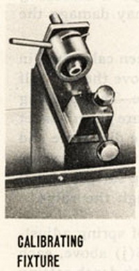
(i) Set the index pointer at the 500 foot mark and place the mechanism in calibrating fixture. |
|
|
(j) Apply water pressure with control valve C. Allow pressure to increase at the rate of approximately 6.5 psi until the valve opens wide. This can be determined by a sudden rush of water a compared with a slight trickle which occurs at a few pounds before the actual opening point. The opening pressure should be noted. Then the pressure should be gradually reduced until the valve clo-ses, at which point the pressure should also be noted. The valve should open at a pressure of 222 psi, plus or minus 10 psi, and the closing pressure should be at least 50 psi below that at which it opened. If the valve open-ing does not occur within the required limits, the valve spring tension should be changed by turning the spring adjusting screw through means provided in the calibrat-ing fixture and the performance repeated. |
|
|
The device built into the calibrating fixture should be ca-refully engaged in the slot of the spring adjusting screw, so that changes in spring tension may be obtained by merely turning the nut and not by pushing on it. |
|
|
When the opening and closing of the valve has been ad-justed to fall within the required limits, the applied water pressure should be allowed to drop well below the clos-ing point and then raised to 50 psi below the opening point. Under this condition the valve should not leak more than a medium drip. |
|
|
The following conditions should be cause for rejection. |
|
|
(1) High or low opening point. Remedy: Readjust and reset. |
|
|
(2) Closing in less than 50 psi below opening point. Remedy: Rebuild using another valve stem with sol-dered ball. Check to make sure adjusting screw is provided with a 3/32 inch diameter drilled hole. |
|
|
(3) Chattering and/or leaking badly 15 psi or more below the opening point. Remedy: Rebuild using another valve stem with soldered ball. |
|
 |
(4) Leaking a fast drip at 50 psi below opening point. Remedy: Rebuild using new valve seat. Check beveled edge of orifice through valve seat to make sure it is smooth. Install new gland seal. Tighten packing nut. Check for chips of brass or dirt in valve seat. |
|
When the deep firing mechanism has been satisfactory calibrated to function within the required limits, it should be carefully removed from the calibrating fixture in order not to disturb the postion of the spring adjusting screw. A tag containing notations of test data should be atta-ched to each mechanism. The postion of the spring ad-justing screw should be marked and, as soon as practi-cable, the screw should be locked in place with a spot of solder to prevent any change in its position which would destroy the calibration. Care should be taken not to overheat the mechanism during the soldering operation. Excessive heat may damage the gland seal. |
|
|
(k) After assembled pistol has been calibrated in accord-nace with paragraph 7, remove the two self tapping screws holding dial plate. Test packing nut for tightness. Assemble dial plate paper gasket in place using shellac. Replace the dial plate and secure it in place whith four self tapping screws. Screw heads must be flush with top surface of dial plate. Blow compressed air through the valve. |
|
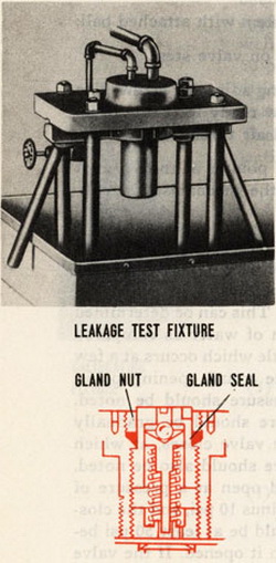
16. After calibration and locking of spring adjusting screw as noted in paragraph 15 (j) above, each deep firing mechanism assembled with depth setting sleeve, gasket, dial plate, index pointer carrier and index pointer should be tested for water-tightness as fol-lows: |
|
(a) With the deep firing mechanism pointer set at the 500 foot mark, place the assembly in test fixture, and subject it to water pressure by control of valve C. |
|
Leakage at a fast drip should not occur around the gasket while the pressure required for valve operation are applied. Leakage around the gasket may readily be determined by water flowing over the outside of the depth setting sleeve. |
|
During this test the deep firing mechanism should be rechecked for compliance with pa-ragraph 15 (j) above, except that no provision is made for changing the valve spring ten-sion. Valve leakage may be readily determined by water flow from the inside of the depth setting sleeve. |
|
After this test satisfactory performance should be noted on attached tag and the as-sembly thoroughly dried by means of compressed air. |
|
|