|
|
| HANDBOOK OF ENEMY AMMUNITION |
| PAMPHLET No. 10 |
| GERMAN, ITALIAN AND JAPANESE AMMUNITION |
| GERMAN MECHANICAL TIME AND PERCUSSION FUZE S/60 Fl |
| (Dopp.Z. S/60 Fl) |
|
The Fuze is used in H.E. shell and the F.H.Gr. 40 Nb. (smoke shell) for the 10.5 cm l.F.H. 18 (gun-howitzer) |
|
The time mechanism is of the centrifugally operated type with a maximum time of running of 60 seconds and is designed to prevent functioning at settings of less than approxima-tely one second. The explosive content consists only of an igniferous detonator which serves for both the time and the percussion action. When functioned by percussion, the pellet carrying the detonator is released from the control of the time mechanism on im-pact. |
|
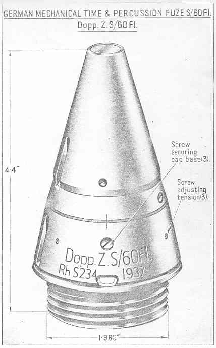
The external appearance of the fuze differs from the mechanical time fuze of the S/30 type (see Pamphelt No. 8) in that the top of the cap is flat and is closed by a metal disc. The fuze is identified by the stamping "Dopp.Z. S/60 Fl.", just above the flange. The stamping "Fl" and the flat top distinguishes this centrifugally operated type from the Dopp.Z. S/60s which is similar in appearance but is operated by a clock spring. |
| The weight of the fuze is approximately 1 lb. |
|
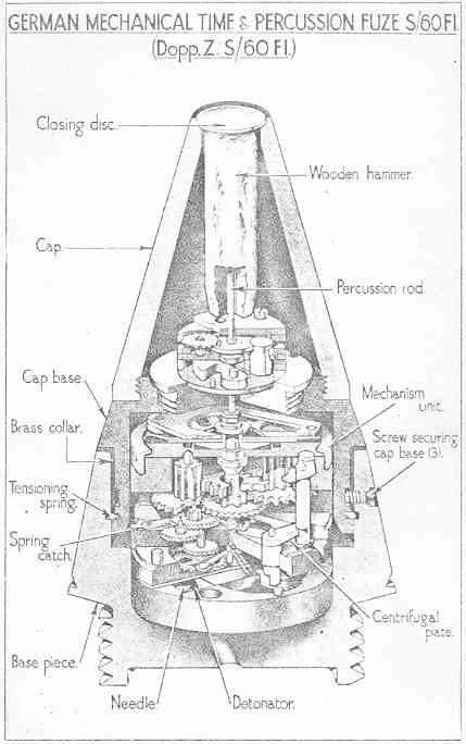
The main components of the fuze consist of the body or base piece, the cap base, the cap, the time mechanism and the percussion mechanism. |
|
The base piece is screwthreaded externally below the flange for insertion in the shell and has a large cylindrical recess in which the time mechanism is located. A brass cylinder is fitted to line the wall of the recess and below this cylinder a circular groove is formed in the wall to correspond with a similar external groove in the cap base. A spring wire with four semi-circular bends is fitted within these two grooves to tension the cap base and the cap. For the adjustment of the tensioning during assembly, three small screws are fitted from the exterior at equally spaced positions around the groove in the body. Semi-circular recesses are formed in the groove at the points where the screws bear on the bends in the tensioning spring. Three larger screws are also inserted through the wall of the body and the brass liner to engage a second groove in the cap base and thus secure it to the body without preventing the rotation necessary in setting the fuze. Inside the recess, at the base, there are two small recesses to receive corresponding locating studs on the base of the time mechanism unit. An inclined flash channel is formed near the centre of the base and three holes are provided for the bolts securing the time me-chanism unit. |
|
|
|
The cap base consists of an aluminium sleeve which fits into the recess in the body and surrounds the time mechanism unit. The sleeve is flanged near the top to coincide with the contour of the fuze. Above the flange it is reduced in diameter and screwthreaded externally to receive the cap and internally to receive the percussion mechanism unit. The internal shoulder formed by the reduction in diameter carries the setting pin and the hammer spring. Two circumferential grooves are formed on the outside of the sleeve near the base. The lower groove receives the wire tensioning spring, the upper groove is en-gaged by the securing screws in the body. |
|
The cap is cone-shaped with a flat top which is closed by a metal disc. Internally, at the base, it is screwthreaded for assembly with the cap base. |
|
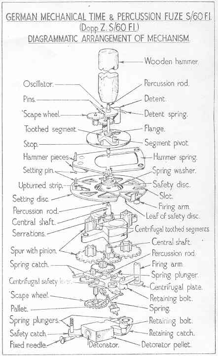
The time mechanism is assembled in a cylindrical unit of superimposed plates of brass and aluminium and consists of a central shaft rotated by two centrifugally operated segments and controlled by an escapement. The shaft carries a slotted setting disc which releases the firing arm when the slot in the disc has been rotated into alignment with the arm. |
|
The central shaft is tubular with a spur near the lower end and a pinion at the base. The upper part of the shaft is reduced in diameter to receive the bush carrying the setting and safety discs and is screwthreaded to receive the tensioning and locking nuts. The sloping shoulder formed by the reduction in diameter is serrated to engage with similar serrations on the bush so that the bush is located to the shaft. The percussion rod of the percussion mechanism passes through the tubular shaft. |
|
Two weighted centrifugal toothed segements, each pivoted on a semi-circular disc, are enmeshed with spurs which, through pinions formed at their base ends, drive the central shaft. |
|
A train of four spurs and pinions transmits the motion of the pinion at the base of the central shaft to the escapement wheel. The wheel is engaged by two vertical arms on the pallet which is weighted at each end and controlled by a straight adjustable hair spring. The pallet is located at one end by centrifugal safety safety lever which is fitted with a weighting pin and held by a retaining spring. A step formed on the pivoted end of the lever is engaged by the end of the spring when the lever has swung to the armed position. |
|
The setting disc, with the safety disc beneath it is carried by a bush which fits over the upper end of the central shaft. The bush is in the form of a sleeve with a hermispherical flange at the base. The sleeve is serrated at the lower end to engage a corresponding shoulder on the shaft so that it rotates with the shaft. The safety disc is keyed to the flange of the bush and is of smaller diameter than the setting disc but has a projecting leaf at one part of its circumference which can close the slot in the setting disc and so prevent the operation of the firing arm. The setting disc is capable of rotation on the bush but is tensioned by a saucer-shaped spring washer which is compressed by the tensioning and locking nuts. An upturned forked strip on the setting disc engages the setting pin in the cap base above. A curved slot, diametrically opposite the strip, provi-des clearance for a projection on the firing arm and thus permits the arm to rotate when these two are in alignment. |
|
|
|
The retaining bolt consists of a short vertical shaft with an arm at the top which is held by the firing lever. Near the base of the shaft a flat surface is formed which keep the re-taining catch in engagement with the detonator pellet. |
|
The retaining catch consists of a flat hook which is pivoted at one end and engages a notch in the detonator pellet at the other. |
|
The detonator pellet is contained opposite to a fixed needle in a transverse rectangular slot in the base of the mechanism unit and consists of a rectangular brass pellet carrying a detonator at one end. Near the other end, which is held against a spring plunger, two vertical notches are cut in the sides. A flash channel leads from the detonator to the base of the pellet. In addition to the retaining catch, the pellet is also held by a centrifu-gal safety catch. |
|
The safety catch, located by a spring plunger in a channel cut in the side of the pellet slot, consists of a flat brass plate shaped at its inner end to engage a corner of the de-tonator pellet. A recess is formed in the catch to receive the rounded head of the spring plunger. |
|
The percussion mechanism is contained mainly in the cap and consists of a wooden ham-mer fitted over a percussion rod which is supported by a centrifugally operated mecha-nism under the control of an escapement. The lower end of the rod bears against the in-clined projection on the spring catch and when pushed in release the centrifugal plate. The outward movement of the plate results in the release of the detonator pellet. |
|
The percussion rod fits into a recess in the base of the wooden hammer and has a flan-ged sleeve fixed near its upper end. The flange is supported by a toothed segment which is pivoted at one end and is enmeshed with a spur carrying a pinion. The pinion is enme-shed with a spur carrying the escapement wheel which works in conjunction with two pins on an oscillating disc. The disc is fitted loosely over the upper end of the percussion rod and has two semi-circular recesses in its periphery. One of the recesses has a pin near each end to engage the escapement wheel, the other receives one side of detent in the form of a solid cylindrical pellet with a notch in its outer side. The detent is sup-ported by a straight wire engaging the notch. |
| Time Action |
|
The time of running is governed by the size of the arc extending clockwise between the curved slot in the setting and the position of the vertical projection on the crosshead of the firing arm. The fuze is set by turning the cap with the aid of a graduated setting key. The rotation of the cap with its base is transmitted to the setting disc by the setting pin engaging in the forked strip of the setting disc whilst the safety disc is held keyed to the stationary bush on the central shaft. The curved slot in the setting disc is thus rotated clear of the projecting leaf on the safety disc. The widht of the leaf and its position re-lative to the projection on the crosshead of the firing arm are so arranged that the leaf still closes the slot at setting up to approximately one second and so prevent the fuze functioning dangerously near the gun. |
|
On acceleration the hammer spring sets back and flattens down the forked strip on the setting disc, thus disengaging it from the setting pin. During flight the centrifugal safety lever is swung clear of the pallet and releases the escapement mechanism. The toothed segments, operated by centrifugal force, then swing outwards and, through their spurs and pinions, rotate the central shaft with the disc assembly under the control of the es-capement. Whilst this movement is in progress the weighted end of the crosshead on the firing arm tends to swing out-wards but is prevented from so doing by the vertical pro-jection at the other end bearing against the edge of the rotating setting disc. Also, the spring plunger of the safety catch is eased from the catch by deceleration and the catch is thrown clear of the detonator pellet by centrifugal force. |
|
When the slot in the setting disc has rotated into alignment with the vertical projection on the corsshead the firing arm is revolved to the extent permitted by the slot and the recess cut in its lower part is turned to provide clearance for the arm of the retaining bolt. The arm then swings outwards and the flat surface on the shaft releases the retai-ning catch. The catch is thrown clear of the detonator pellet which is driven on the needle by its spring plunger. |
|
|
| Percussion Action |
|
With the fuze set for percussion, that is to the safety mark on the graduated setting key, the leaf on the safety disc closes the slot in the setting disc. Thus although the disc assembly is rotated during flight, the two discs move together and the slot remains closed. |
|
On acceleration the detent locking the oscillator set back and releases the oscillator. The toothed segment supporting the flange on the percussion rod is swung outwards by centrifugal force. This movement is controlled by the escapement mechanism and limited by a stop pin. The percussion rod is then supported by the creep resulting from decele-ration. |
|
On impact the percussion rod is driven in by the hammer. The thrust of the rod on the inclined projection of the spring catch disengages the catch from the centrifugal plate which is then free to move outwards making with it the base end of the firing arm. This movement of the firing arm sets free the arm on the retaining bolt and thus releases the retaining catch and the detonator pellet. |
|
|