|
|
| U.S.N.B.D. - UNITED STATES - BOMBS AND FUZES; PYROTECHNICS |
| SECTION IV - PYROTECHNICS |
| PART I - AIRCRAFT PYROTECHNICS |
|
DATA: |
U.S. NAVY FLARE |
|
|
|
Mk 4 FLARE |
|
|
OVERALL LENGTH |
27 in. | |
|
DIAMETER OF CASE |
4.75 in. | |
|
WEIGHT |
18 lb. | |
|
BURNING TIME |
3 min. |
|
|
INTENSITY |
300,000 candle |
(And Mods) |
| power | ||
|
COLOR |
White |
|
|
MAXIMUM EFFECTIVE RELEASE |
||
|
ALTITUDE |
1200-1500 ft. | |
|
RATE OF FALL AFTER IGNITION |
350 ft./min. |
|
USE: |
|
1. Primarily, it is used to illuminate an area to permit the landing of aircraft. |
|
2. Occasionally, it is used for recommoitering, bombing, and blinding anti-aircraft de-fenses. |
|
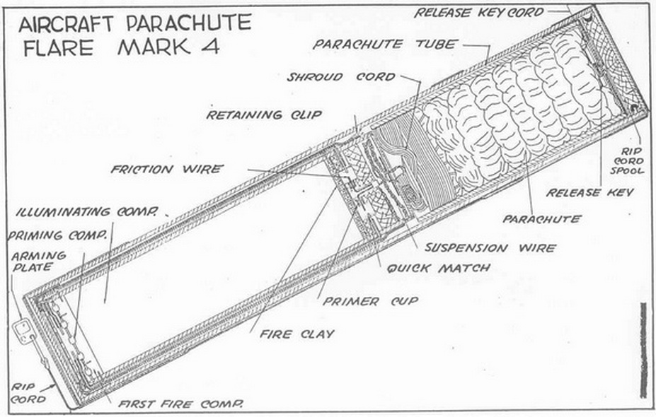
DESCRIPTION: |
|
The complete flare consists of a parachute and illuminant contained in a shellac-im-pregnated chip board tube closed at the ends by chip board discs which are held in place by gummed cloth and sealed with paraffin. There are two metal steadying bands fastened around the case against which the steadying forks of the bomb rack rests. The complete flare is issued in a water-proof metal container. |
|
RELEASING METHOD: |
|
1. Bomb rack or shackle release: Mk 50 and Mk 51 racks; Mk 3 (and Mods.) shack-les; Mk 4, Mod. 2 and above shackles; Mk 5 and Mods. shackles. |
|
For this type of release support bands are required, being shipped with the flare and attached in positions indicated on the flare. The Mk 35 and Mk 41 racks are not desig-ned to operate with less than 100 lb. load and should not be used with this flare. |
|
2. Adapter Release (chuts or holder): The flare is inserted into the adapter with the heavy end down and the rip cord is secured on a hock in the plane. The flare is releas-ed by a switch from the cockpit. |
|
3. Cockpit Release (Not recommended except is emergency): An additional 10 feet of rip cord is attached to the arming plate of rip cord and the other end is secured to some substantial part in the plane. The flare is released in a vertical position, heavy end down, with as much downward velocity as possible so that it will be well clear of the plane when rip cord is taut. |
|
OPERATION: |
|
As the flare is dropped from the plane, the arming plate of the rip cord is retained by the plane and the rip cord is pulled from the side of the flare case to which it is faste-ned by gummed cloth tape. As the flare continues to fall, the rip cord, which is wound around a wooden spool inside the end of the flare case, is unwound tearing away the end of the flare case. The end disc and spool fall away as the parachute tube is pulled from the flare case and retained by the rip cord. The parachute is pulled out of its tube by the weight of the illuminating and flare case and causes the parachute and para-chute shrounds to straighten out. When the parachute and parachute shrouds are fully extended, a small cord attached to the release key pulls the release key down allowing the rip cord to slip through the key and the flare falls free. |
|
An ignition wire is attached to the suspension cable in such a manner that it is pul-led before the cable is fully extended. Four friction wires are attached to the ignition wire and run through primer cups of match compound. This ignites a double quickmatch train which burns down the outside of the illuminant case and ignites the primer compo-sition which in turn ignites the first fire and illuminant. When the parachute opens, the illuminant is pulled out of the flare case, and flare case falls clear. Full suspension and ignition occur about 30 - 50 feet below the plane. |
|
|
|
|