|
|
| U.S.N.B.D. - UNITED STATES - BOMBS AND FUZES; PYROTECHNICS |
| SECTION III - BOMB FUZES |
|
DATA: |
ARMY-NAVY ATHWARTSHIP FUZE |
|
|
|
AN-Mk 234 |
|
|
BOMBS USED IN |
Depth bombs, Mks. 17, 29, | |
|
|
37, 38; AN-Mks. 17, Mod. 2 | |
|
|
41, 44, and 47. | |
|
FUNCTIONING |
Water pressure at depth |
(Obsolete) |
|
|
set for 25, 50, 75, 100, |
(Hydrostatic) |
|
|
or 125 feet of water. |
Fuze is suspended from use |
|
ARMED CONDITION |
Partially armed when arm- | |
|
|
ing wire is pulled and jump- |
|
|
|
out pins are ejected. Arm- |
|
|
|
ing completed at 12-15' of |
|
|
|
water when primer & deto- | |
| nator are aligned with firing | ||
| pin. | ||
|
FUZES USED WITH |
AN-M103, AN-Mk 219, or Mk 221 in nose, and Mk 229 in tail in | |
|
|
650 lb. depth bombs. | |
|
ARMING TIME |
Partially armed immediately after arming wire is pulled when | |
| jump-out pins are ejected, complete arming time dependet on | ||
| travel through water until depth of 12-15' is reached. | ||
|
OVERALL LENGTH |
Firing assembly (Pistol) - 6.9" | |
| Extender assembly - 9.9" | ||
|
MAX. BODY DIAMETER |
3.6" | |
|
MATERIAL |
Bronze, brass, steel, and aluminum |
|
|
GENERAL: |
|
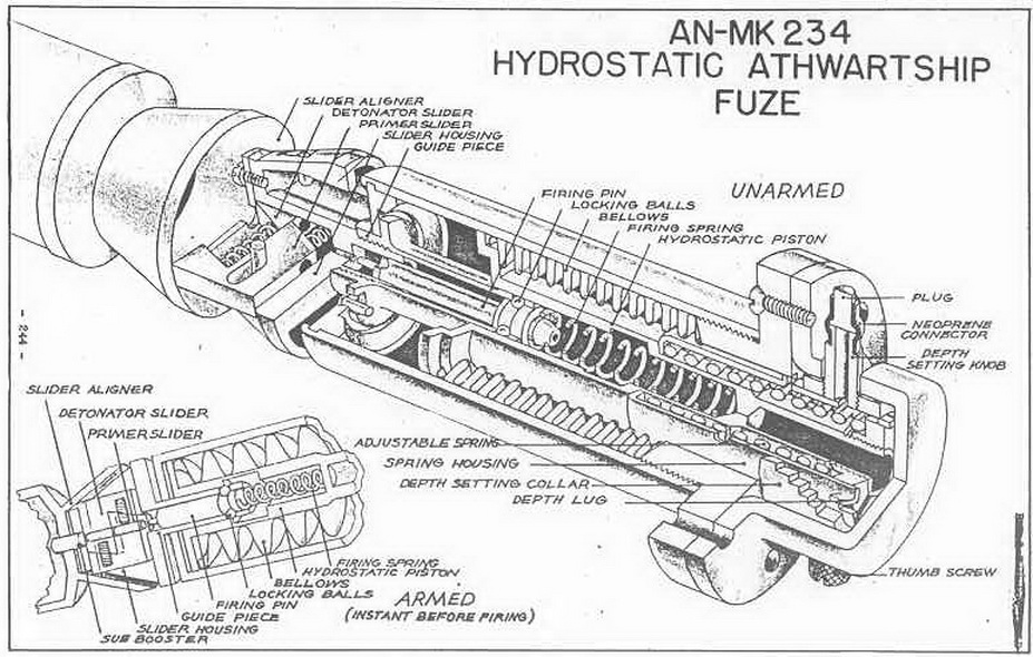
This fuze is essentially the same as the AN-Mk 224, being an athwartship fuze consisting of the pistol, booster, and booster extender. The firing assembly and booster extender are inserted in the athwartship tube of the depth bomb from opposite sides. The AN-Mk 234 differs from the AN-Mk 224 in that it has an external setting device and does not require disassembly to effect depth variations in functioning. |
|
The depth setting is accomplished by varying the amount the adjustable spring must be compressed by the hydrostatic piston as the bellows expand. If a deep setting is desired, the depth setting collar is rotated so that a shallow step on the collar would be positioned under the spring housing depth lug. Thus, the depth lug would engage the collar shortly after entering the water, and the bomb would have to sink farther be-for the water pressure could overcomes the spring restistance. If a deep step were po-sitioned under the lug, the hydrostatic piston could move farther before encounterring restistance from the spring. Until the lug is engaged, the spring housing rides inward with the hydrostatic piston, but as soon as the lug is engaged the spring housing no longer move with the piston and the spring resistance must be overcome. |
|
OPERATION: |
|
(1) Action in Booster extender: When the bomb is dropped from the plane, the arm-ing wire to the booster extender is withdrawn from the jump-out pin. The jump-put pin is thrown out by its spring; the booster spindle is freed, and water is permited to enter the hole created by the jump-out pin. The water expands the bellows until it over-comes the pressure of the spring acting against the locking slide and booster spindle. The locking balls are forced into an enlarged groove in the fuze and the booster and sli-der aligner move inward, aligning the primer and detonator sliders, as described in the operation of the AN-Mk 224 (see page 243 for diagram and explantion). |
|
(2) Action in the Pistol: As the arming wire pulls free, is extracts the plug and neo-prene connector, permitting water to enter the fuze when bomb immerses in water. The water acts against the flanged base of the hydrostatic piston and as the pressure in-creases expands the bellows. The hydrostatic piston, adjustable spring, and spring hou-sing all move inward until the depth lug engages the step on the depth setting collar which has been positioned opposite it. At this point the spring housing no longer moves inward. The hydrostatic piston continues to move inward under pressure of the water, but its movement is restricted by the restistance of the adjustable spring. Meanwhile, the movement of the hydrostatic piston compresses the firing spring, and when the en-larged groove in the piston comes opposite the locking balls the firing spring forces the balls out, forcing the firing pin against the primer. The primer fires the detonator, which sets off the sub-booster of tetryl, the booster and the main charge. |
|
REMARKS: |
|
For a diagram of the extender and booster assembly, and for a more complete ex-planation of this assembly, turn to page 242 and 243. |
|
|
|
|