|
|
| U.S.N.B.D. - UNITED STATES - BOMBS AND FUZES; PYROTECHNICS |
| SECTION III - BOMB FUZES |
|
DATA: |
ARMY-NAVY ATHWARTSHIP FUZE |
|
|
|
AN-Mk 224 |
|
|
BOMBS USED IN |
Depth bombs, Mks. 17, 29, | |
|
|
37, 38; AN-Mks. 17, Mod. 2 | |
|
|
41, 44, and 47. | |
|
ARMED CONDITION |
When jump-out pins are |
(Obsolete) |
|
|
out, fuze is partially armed. |
(Hydrostatic) |
|
|
Arming completed at 12-15' |
Fuze is suspended from use |
|
|
depth of water when primer | |
|
|
and detonator are aligned |
|
|
|
with firing pin. |
|
|
FUNCTIONING |
Water pressure at depth |
|
|
|
set for, 25, 50, 75, 100 or | |
| 125 feet of water. | ||
|
FUZES USED WITH |
AN-M103, AN-Mk 219, or Mk 221 in nose, and Mk 229 in tail in | |
|
|
650 lb. depth bombs. | |
|
ARMING TIME |
Partially armed when dropped and arming wire is pulled, com- | |
| plete arming time depending on travel through water until depth | ||
| at which it is set to function is reached. | ||
|
OVERALL LENGTH |
Pistol assembly - 6.9" | |
| Booster extender assemblies - 9.9" | ||
|
MAX. BODY DIAMETER |
3.6" | |
|
MATERIAL |
Bronze, brass, steel, and aluminum |
|
|
GENERAL: |
|
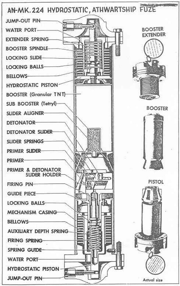
This is an athwartship fuze, and is assembled in three subassemblies; pistol, booster, and booster extender. The pistol is marked for the depth at which it is set, and con-tains the firing mechanism and the detonator sliders. Desired depth setting is made by inserting in the proper firing pin spring and auxiliary spring if necessary, with settings of 25, 50, 75, 100, or 125 feet possible. The following table shows the springs to use for the various depth settings: |
|
Depth |
Spring Color |
||
|
25 feet |
Yellow |
||
|
50 feet |
Black |
||
|
75 feet |
Black & green |
||
| 100 feet |
Yellow & red |
||
|
|
125 feet |
Black & red |
|
|
The yellow and black springs as selected actuate the firing pin and in addition serve a depth controlling prupose. Green and red springs are auxiliary depth control springs and do not actuate the firing pin. The booster extender fits into the opposite end of the transverse tube in the depth bomb. |
|
OPERATION: |
|
(1) Action in Booster extender: As the arming wire is pulled, the jump-out pin is for-ced out by its spring, and water enters the assembly as the bomb because immersed. The water expands the bellows until it overcomes the pressure of the spring acting against the locking slide. The booster spindle and the locking slide are held together by the locking balls between them. When the water pressure has forced the piston, locking slide, and spindle inward sufficiently for the locking balls to slip into the enlarged groove in the fuze body, the entire booster extension is then free to move then remaining inch toward the pistol. The hollow-cone shaped slider aligner, bearing inward against the L-shaped primer and detonator sliders, forces them inboard against their springs, this lin-ing up the explosive train. |
|
(2) Action in Pistol: As the water pressure increases and overcomes the tension of the firing and auxiliary depth springs in the piston, the bellows extend and the base of the hydrostatic piston moves down over the firing pin guide piece. This action compres-ses the firing and auxiliary depth springs, and when the enlarged part of the hydrostatic piston comes opposite the locking balls they are forced out by the spring pressure, freeing the firing pin to be forced against the primer. The L-shaped primer and detona-tor sliders will have been lined up with the firing pin by the action of the slider as des-cribed in (1). |
|
REMARKS: |
|
If the booster extender fails to function properly and force the slider aligner over the primer and detonator sliders, the fuze cannot function. The slider aligner which holds them in the armed position is prevented from returning to the unarmed position by the locking slide, which locks after the locking balls are forced out from the spindle in the extender. |
|
|
|
|