|
|
| LAND MINES |
| Section III |
| ANTITANK MINES AND FUZES |
|
11.2 MINE, ANTITANK, H.E., HEAVY, T6E1 |
|
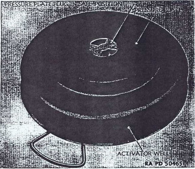
a. General. The complete mine (fig. 4.2) consists of the loaded mine body, the fuze, and the pressure plate plug. In addition to the fuze well, two threaded activator wells are located in the mine body, one in the bottom and one on the side. |
|
|
|
Figure 4.2 - MINE, antitank, H.E., heavy, T6E1 showing
pressure plate |
|
b. Description. |
|
(1) The round steel mine body has a base diameter of 13 inches and is loaded with appoximately 12 pounds of TNT. It is painted olive-drab, with markings in yellow. Both activator wells are threaded to reveice the M1 activator (fig. 4.5). The carrying handle is attached to the bottom of the mine. Assembled to the mine body is a round pressure plate, 7½ inches in diameter, containing the reversible pressure plate plug which covers the fuze well. The pressure plate is supported internally by circular (Belleville) springs. The maximum high of the mine is 3 3/5 inches. This mine is not affected by stones, dirt, or moisture. |
|
|
|
Figure 4.3 - MINE, antitank, H.E., heavy, T6E1 showing
pressure plate |
|
(2) Upon issue the pressure plate plug is screwed in the pressure plate in SAFE position (fig. 4.2). When the plug is unscrewed and removed, the fuze retaining spring is exposed at the top of the fuze well. After the fuze is inserted, the plug is reversed and inserted so that the solid center portion of the plug rest directly over the top of the fuze. The plug will then be in ARMED position (fig. 4.3). Pressure of 350 pounds or more on the pressure plate, with the plug in ARMED position, will cause the fuze to function and deto-nate the mine. |
|
(3) FUZE, chemical, mine, antitank, T8E1 (fig. 4.4), is armed for firing when the safety key is withdrawn. The safety key will not be removed except immediately before placing the fuze in the fuze well. |
|
|
|
Figure 4.4 - FUZE, chemical, mine, antitank, T8E1. |
|
(4) ACTIVATOR, M1 (fig. 4.5), is a plastic adaptor approximately 2 inches long. It has a threaded plug in the head and a tetryl booster charge in the cylindrical cap at the oppo-site end. The plug and cork gasket are removed from the head to accommodate any standard firing mechanism. The base is threaded to fit into the side or bottom activator well of the mine. This activator must be used to assembled a firing mechanism to the mine. When fired, the primer of the firing mechanism ignites the activator booster charge which detonates the mine. |
|
|
|
Figure 4.5 - ACTIVATOR, M1 |
|
c. Fuzing of the Mine. |
|
(1) Remove pressure plate plug. |
|
(2) Inspect fuze well to be certain it is clear of any foreign matter. |
|
(3) Remove safety key from fuze. |
|
(4) Insert fuze in well with head up. Avoid pressure directly on top of fuze head. Push fuze down until retainin spring clicks around top of fuze body. |
|
(5) Replace pressure plate plug in the mine in ARMED position (fig. 4.3). Screw plug in handtight. |
|
NOTE: Functioning of the fuze may be prevented by installing the pressure plate plug in SAFE position. |
|
d. Defuzing. |
|
(1) Remove pressure plate plug by unscrewing it in a counter-clockwise direction. |
|
(2) Loop a piece of wire under the fuze spring (fig. 4.4). Withdraw fuze and replace safety key. The fuze may also be removed by grasping the edges of the spring with long-nosed pliers. |
|
(3) Replace pressure plate plug in SAFE position (fig. 4.2), and screw in handtight. |
|
e. Antiremoval Device. |
|
(1) INSTALLATION. Any standard firing mechanism may be attached to this mine, after the mine is fuzed. Use the M1 activator as described below. CAUTION: Fuze the mine (see c above) before installing any antiremoval devices. Be sure the pressure plug plate is in ARMED position during this installation. |
|
(a) Remove tape and shipping sleeve from activator well. |
|
NOTE: Care must be exercised not to exert pressure on the pressure plate. |
|
(b) Inspect well to be certain it is free of foreign matter. |
|
(c) Remove plug and cork gasket from head of activator. Screw activator handtight in-to well. |
|
(d) Screw firing mechanism handtight into activator. |
|
(e) Plant the mine and arm firing mechanism in accordance with type used (pars. 24, 25). |
|
(2) REMOVAL. If the mine is to be picked up. all antiremoval devices must be disarmed and removed as follows: |
|
(a) Replace all safety devices in the firing mechanism. |
|
(b) Cut trip or anchor wires. |
|
(c) Unscrew firing mechanism from activator. |
|
(d) Remove activator. Replace plug and gasket in head of activator. |
|
(e) Defuze mine (see d above). |
|
f. Packing. Each mine is packed separately in an olive-drab square metal crate. A metal can containing one T8E1 is packed in the crate with the mine. The crate is 13 3/16 in-ches square and 4½ inches high. The complete pack weighs 30 pounds. |
|
|