|
|
| GERMAN UNDERWATERS ORDNANCE MINES |
| Chapter 11 - INFLUENCE MINE UNITS - SVK AND LUFTWAFFE |
| Section 4 - MAGNETIC-ACOUSTIC COMBINATION UNITS |
| MA 1, MA 1a, MA 1st, MA 2, and MA 3 MINE UNITS |
|
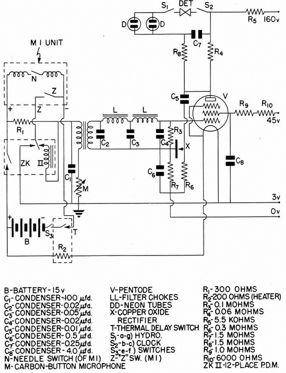
MA 1. The MA 1 unit circuit is shown in figure 200. The acoustic component is trig-gered by the magnetic component for a period determined by the time interval set by the heating of a thermal delay switch. The acoustic component contains a single pentode vacuum-tube, which, in its output circuit, fires the detonator without use of a relay system. The operation of circuit is as described below. |
|
Arming. Arming is accomplished by closure of the hydrostatic clock switches which are indicated in the circuit diagram as S1, S2, and S3. Closure of S1 and S2 puts the de-tonator into the circuit. Closure of S3 connects battery B into the circuit. When B is con-nected by S3, the magnetic M 1 component goes through latitude adjustment in the usual manner through the normally-closed contact of thermal delay switch T. When lati-tude adjustment is complete the unit is ready for actuation. |
|
Triggering. Triggering is accomplished by the magnetic component, which is normally alive. If a P.D.M. (ZK II) is fitted, the "blind" actuations (11 maximum) need only be mag-netic, in which closure of the Z switch of the M 1 unit allows battery B to energize the trigger coil of the ZK II and advance the P.D.M. one stage. During the cycle of 120 se-conds, the normally-closed switch of the ZK II breaks holding current to the M 1 unit and restores the original condition of the circuit. When the "blind" actuations are run off on the ZK II, the next magnetic actuation will trigger the acoustic component. The M 1 component is modified sligthly when used in this combination to produce a higher magne-tic sensitivity averaging approximately 5 mg. This is done by weakening the latitude-ad-justment hairspring and slowing down the latitude-adjustment clockwork. When a mag-netic actuation now takes place, closure of the Z switch: |
|
1. Energizes microphone M through resistor R1. |
|
2. Energizes the heater of pentode V. |
|
3. Energizes the heater R2 of thermal delay switch T. |
|
Acoustic Actuation. Sound falling on the microphone is transformed into electrical im-pulses in the secondary of the microphone transformer and fed to a low-pass L/C filter. The filtered output is loaded across R3. Vacuum tube V is biased as a linear amplifier, and the amplified signal appears in the output circuit of V. Some of the amplified signal is fed back to the grid circuit by condenser C5 to rectifier X. This rectifier is connected to R6 and R7, in such a manner that a rectified signal potential appears across R7, thus making the grid potential of V more positive. This results in greater conductivity of V and a greater plate current through resistor R4. The potential drop across R4 is loaded across C7 through R8, which rovides a short charging delay. When C7 charges to a potential of approximately 110 volts, the neon tubes (DD) break down and C7 discharges through the detonator, firing the mine. |
|
De-Energizing. If, after triggering and energizing of the acoustic component, no acoustic component, no acoustic actuation occurs, heating of the thermal delay switch T due to heater R2 causes the contact of T of break. When this contact breaks, all com-ponents of the acoustic component energized by magnetic actuation are de-energized, since the return of battery B is thereby broken. Also, the holding current to the magne-tic component is broken, and all components of the circuit are restored to normal. Since R2 is also de-energized, the thermal delay switch recloses shortly after opening. Approx-imately 45 seconds is necessary for the T contact to open from an originally cold condi-tion. However, if repeated magnetic actuation takes place, the period will be according-ly shortened. |
|
|
|
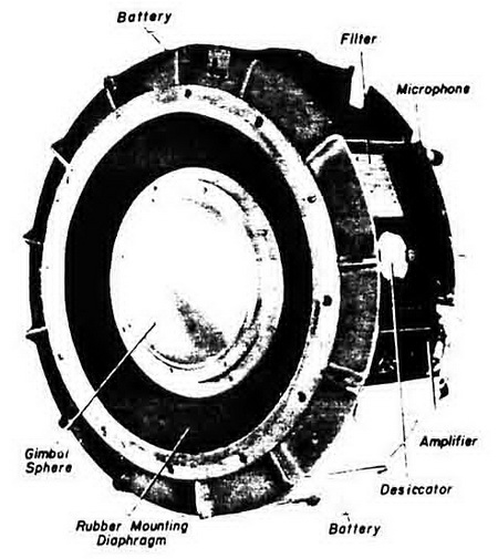
Figure 207 – MA 1 Unit |
|
|
|
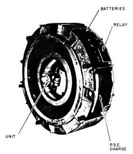
Figure 208 – MA 1 Unit |
|
|
|
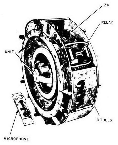
Figure 209 – MA 1 Unit |
|
|
|
|