|
|
| GERMAN UNDERWATERS ORDNANCE MINES |
| Chapter 11 - INFLUENCE MINE UNITS - SVK AND LUFTWAFFE |
| Section 3 - ACOUSTIC MINE UNITS |
| MICROPHONES |
|
Microphone Circuit. The typical microphone circuit was very simple and consisted of a microphone battery, resistor, clock switch and transformer. The circuit was activated by hydrostatic clock switch closure, and the mine remained alive until the battery was dead. The sensitivity of the mechanism depended on battery potential, and German figu-res on life indicate 3 - 6 months maximum. This circuit could be modified to suit the unit to which fitted, but it always remained basically the same. |
|
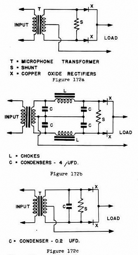
Rectifier-Filler Circuit. The first acoustic unit was made with no attempt to limit the operation frequencies. The signal current was shunted (to determine sensitivity) and re-lays, figure 172a: as a result, a secondary resonance at approximately one kc was pre-sent. It was found that, although a minor resonance, mines with this must be swept with underwater signalling apparatus which operated near one kc. A large number of such mines were fired in the vicinity of light-shpis, etc. To counter this effect, some circuite were fitted with L/C filters of a low-pass type which caused cut-off at approximately 400 cps., figure 172b. As well, some of the later types were fitted with only a low-capacity condenser, figure 172c, when used with a microphone with a narrow band width. |
|
Figure 172 – Parts a, b, and c – Rectifier-Filter Circuits |
|
|
|
|