|
|
| GERMAN UNDERWATERS ORDNANCE MINES |
| Chapter 11 - INFLUENCE MINE UNITS - SVK AND LUFTWAFFE |
| Section 3 - ACOUSTIC MINE UNITS |
| MICROPHONES |
|
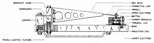
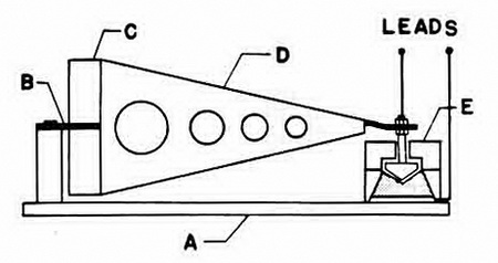
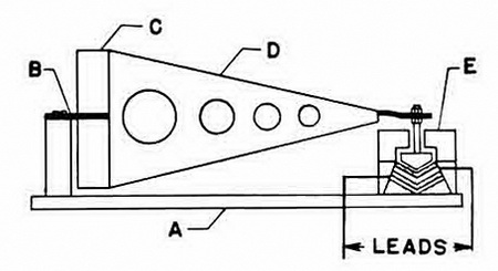
With one experimental exception, all German sonic acoustic mine systems (including combinations) used carbon-button microphones. All the units described herein, except A 107 (Goepel), used the cantilever-type microphone which existed in two basic forms. The "normal" microphone, as its name implies was used for acoustic unit designed against normal target vessels. The "stumpf" microphone had somewhat different characteristics and was designed for use with acoustic units modfied to be anti-mine-sweeper units. First attempts to make insensitive units were confined to putting low-resistance shunts in the microphone circuit, but unfavorable microphone characteristics caused this proce-dure to be abandoned. Both types of cantilever microphones were mounted securely on a base bolted inside the mine. Through a spring suspension, the assembly was mounted free to move due to minecase vibrations. An arm amplified the motion of the resonant mass and transferred it to a carbon button. In the case of the normal microphone, figure 170a, arm motion was transferred directly to the upper electrode and vibrations thus caused direct compression and expansion of the carbon granules. In the "stumpf" micro-phone, figure 170b, arm motion was transferred to a block which caused compression and expansion of the large body of carbon granules between two electrodes located in the carbon. These microphones were developed in 943, and mass production was started early in 1944. They were used only in the A 1, A 2, A 4, A 104 and A 105. |
|
Resistance output for the normal microphone was 50 cps. |
|
Resistance output for the "stump" microphone was 100 cps. |
|
The microphones VM 1, VM 2, VM 3 had no shock mounting; VM 4 had shock mount-ing; VM 5 Stu. had a very coarse setting. |
|
Figure 169 – German Acoustic Mine Microphone |
|
|
|
|
|
|
|
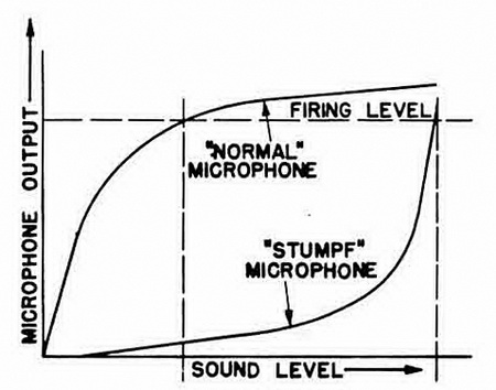
The relative characteristics of the two microphones are shown in figure 171. A normal microphone response is nearly flat, because of overloading after the point normally used for firing; thus, it was unsuitable for shunting and use in anti-mine-sweeper circuits. The "stumpf" microphone, however, had an entirely different characteristic that rendered it suitbale for such systems. This was a principle of microphone construction known to the Germans as "Querstrom" (cross-current). |
|
|
|
The cantilever type of microphone construction was known to the Germans as the "Vibrations Mess-systeme" or vibratons-measuring-system. It had the advantage that it was not exposed to the water and its operating point was not changed by depth. How-ever, it was somewhat less sensitive than some later types developed by the Germans. Every cantilever microphone was received at the mine depot with a group of shunts de-signed for insertion into the circuit when the microphone was fitted in the mine. The nor-mal microphone was received with four shunts, (for different sensitivities) and the "stumpf" microphone with one shunt. |
|
The first German microphones had a peak resonance at approx. 200 cps., with a band width of approx. ± 75 cps. Because of constant effort and improved construction met-hods, the normal resonance was reduced to approximately 90 cps. with a band width of approx. ± 5 cps. The "stumpf" microphone, it was expected, would have very sharp re-sonance at several points in the spectrum. The improvements in the cantilever micro-phone resulted in smaller size, stronger construction, and lower frequency resonance to make sweeping more difficult. |
|
The two A 107 (Goepel) units, used the D 102 Mi microphone (Hasag-Mikrophon). This microphone was a converted D 102 pressure detector, fitted with an external diaphragm and a carbon-button microphone. This mounting was fitted with an equalizing channel which allowed pressure to be equalized on both sides of the external diaphragm. This was the same type of microphone used in the DA 102 series of units and had the advantage that, although its diaphragm was exposed to the water, hydrostatic pressure did not alter the operation point. |
|
|