|
|
| GERMAN UNDERWATERS ORDNANCE MINES |
| Chapter 11 - INFLUENCE MINE UNITS - SVK AND LUFTWAFFE |
| Section 2 - MAGNETIC UNITS |
| M 5 UNIT |
|
The M 5 is a relatively small and simplified dip-needle type unit of the same basic construction as the M 1, and is suitable for mass production. It is fitted with a pendu-lum-tpye anti-countermining switch, and was designed for use in ground mines. Its ope-rational characteristics are similar to those of the M 1, except that it is reported to be capable of dependable setting at a 2.5-mg sensitivty. Its development was undertaken in parallel with that of the M 4, the intention being that the unit which proved more satis-factory would be adopted. The M 4 development was completed first. Since the M 4 unit had the advantage of bi-polarity and repeated latitude setting, and was suitable for use in moored mines, the work on the M 5 was curtailed. |
|
The Unit Frame. The unit frame is a single casting mounted on gimbal rings inside a spherical container approximately eight inches in diameter. The container is fitted with rubber ties that serve as shock absorbers. The unit is so balanced that it assumes a ver-tical position rapidly. All the electrical and magnetic components are mounted on the unit frame except the setting coil (Einstellwicklung) and the setting resistor (Einstellwider-stand). The components mounted of the frame are: |
|
2. The hold-on coil (Haltespule) |
|
3. The pendulum switch (Pendel) |
|
4. The hold-off coil (Abreißspule) |
|
5. The anti-countermining device (Haltemagnet) |
|
6. The therman delay switch (bi-Metal Relais) |
|
7. The five-ohm resistor |
|
The Needle Switch. This switch is a single-pole single-throw type, mounted on knife edges and fitted with four cylindrical permanent magnets. These magnets are approxi-mately 3/8 inch long and are mounted in the same plane on two parallel axes. There are two magnets approximately 1/2 inch apart and parallel to each other at each end of the needle switch casting, and they are so arranged that the parallel axes of the magnets at each end are the same. This arrangement gives the appearance of two parallel magnets 1/2 inch apart, broken in the middle by a gap of about 1/4 inch. The needle axis is fitted with a moving contact outside the magnet housing. Two hairsprings are mounted on the needle axis, one of which is a stabilizer and has no tension when the plane of the magnet is horizontal (switch closed). The other is an adjusting spring which has a large initial tension that serves to hold the needle switch off contact until proper clockwork adjust-ment takes place. Each end of the switch casting is fitted with a wire to which a disc of 1/2 inch diameter is attached. These two discs move in cylindrical wells within the main unit frame, and by means of a loosely fitted "dash-pot" action, provide the needle damp-ing. The needle housing is protected from dust by two small transparent plastic covers. The magnetic moment of the system is the same as for the M 1. |
|
The Hold-On Coil. This coil is mounted on a form on the bottom of one end of the unit frame. It is 5/8 inch in diameter and 1/2 long, and has a resistance of 0.06 ohms. |
|
The Pendulum Switch. This pendulum is of the same type as that used in the M 1 unit, but is much smaller. (1/2 inch in diameter, 2 3/4 inches long). |
|
The Hold-Off Coil. This coil is mounted on a form on the bottom center of the unit frame. It is 3/4 inch in diameter and 1/4 inch long, and has a resistance of 0.4 ohms. |
|
The Anti-Countermining Relay. This relay is a small two-coil type with a single-pole single-throw contact that is normally open, and is mounted on one side of the unit frame. When energized, this relay stops the clockwork escapement by blocking the motion of the escapement arm. The resistance of the relay magnet is 15 ohms. |
|
The Thermal Delay Switch. This switch consists of two bi-metal strips with a normally closed contact between them, each strip being wound with a heater coil, and this switch is a part of the anti-countermining circuit. One of the strips has a four-ohm heater coil and acts as a contact in another part of the circuit. When heated, this strip tends to keep the switch closed. The other strip has a 75-ohm heater coil which, when heated, tends to open the switch. |
|
The Clockwork Escapement. This device is similar to the one used in the M 1 unit with the normal type oscillating arm. When released by the blowing of the magnet-re-lease fuse, this device slowly decreases the tension in the needle hairspring, this pro-cess continuing until the clockwork is stopped by the blowing of the latitude setting fuse. |
|
The Magnet-Release Fuse. This is the ordinary wire type, and, when blown, it per-forms two functions: |
|
1. It unlocks the magnetic switch. |
|
2. It releases the latitude adjustment clockwork escapement. |
|
The Latitude-Setting Fuse. This fuse is the same type as the magnetic-release fuse. When blown as a result of the first closing of the needle switch, it releases a spring-loa-ded arm which: |
|
1. Breaks contact to the setting coil. |
|
2. Makes transient contact to ensure that the needle does not stick. |
|
3. Close the firnal arming circuit to the detonator. |
|
The Setting Coil. The sensitivity-setting coil is wrapped around the inner gimbal ring, and, in conjunction with the sensitivity-setting resistor, puts a RED magnetic bias field on the mechanism during the latitude-adjusting process. The resistance of this is 0.2 ohms. |
|
The setting resistor is plugged into a receptacle on the inner gimbal ring. The value of this resistor determines the sensitivity of the unit when armed. The following are four resistance values for four different sensitivities: |
|
5 mg - |
2,000 ohms |
|
10 mg - |
1,000 ohms |
|
20 mg - |
500 ohms |
|
30 mg - |
335 ohms |
|
Operation of the Unit. When the hydrostatic clock runs off, the battery is connected across the (+) and (-) terminals of the unit, and the magnet-release fuse S1 blows, with the following results: |
|
1. The needle switch is unlocked and is free to rotate on its knife edges. |
|
2. The latitude adjustment escapement is allowed to start. |
|
Rotation of the latitude-adjustment escapement causes gradual decrease in the ten-sion of the needle hairspring. During this process, the sensitivty-setting bial coil, EW, which is in series with the bias coil resistor P, is energized. This determines the amount of RED bias placed on the unit. When the hairspring tension has decreased to the point where the torque on the needle shaft caused by the hairspring is equal and opposite to the magnetic force of the earth's vertical field, the needle switch will be in equilibrium. |
|
When the needle switch M closes, the reduction in restistance causes the latitude-setting fuse S2 to blow and release a spring-loaded arm which, in rotating, breaks the circuit to the sensitivty-setting coil and stops the latitude-adjustment escapement. When the sensitivity-setting coil is de-energized, the RED bias is removed. However, since the hold-on coil HS is energized at this time, the needle switch does not reopen. |
|
Rotation of the spring-loaded arm makes transient contact, energizing the hold-off coil AS through the relay HM. When energized AS removes the needle from its contact and de-energizes HS. Current through HM causes it to close contact, thereby energizing the self-holding circuit through the contact of the thermal delay switch. This condition persists until the 75-ohm heater opens the thermal delay switch, de-energizing HM. Fur-ther rotation of the arm carries it to its limit stop, closing the arming switch which con-nects terminal Z to the needle-switch circuit. The unit is now fully armed. At this time, a RED magnetic field, equal to or greater than the RED bias field, equal to or greater than the RED bias field imposed by EW in adjustment, will close M. The HS coil will hold the needle on contact, and the detonator will fire. |
|
Disturbance of the mine unit actuates the pendulum switch. This switch energizes the hold-off coil, holding the needle off contact, and current is passes through the four-ohm heater, which tends to keep the thermal delay switch closed. If the disturbance occurs during latitude adjustment, the current passing through the HM coil will stop latitude ad-justment, and close the HM self-holding cirucit. The thermal delay pendulum is closed because the four-ohm coil is energized. For this reason, the duration of a protection period is at least equivalent to the duration of the disturbance. |
|
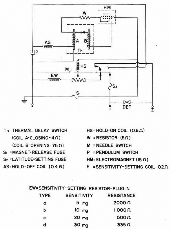
Figure 156 – M 5 Unit Circuit |
|
|
|
|