|
|
| GERMAN UNDERWATERS ORDNANCE MINES |
| Chapter 5 - AIRCRAFT MINES - SVK |
| THE LM MINES |
|
The LMB Mine. The LMB mine was developed during the same period as LMA (1928 - 1934), and was ready for use with the E-BIK by the end of 1938. It was modified in 1940 to suit the mounting of the M 3 unit. The LMB was nearly identical to LMA but carried a larger charge, and the mine case was accordingly longer. Otherwise, except for very small differences, LMA and LMB were identical in method of laying, operational use, and the firing units which could be fitted. LMB was used extensively, perhaps more than any other German influence mine. |
|
Figure 52 – LMB III Mine – Cross Section |
|
|
|
The LMB mine existed in four models, representing progressive development. Originally the mine was known as LMB, but, as in the case of LMA, the earlier two models were considered LMB I and LMB II when the nomenclature was systematized, and later deve-lopments were designated LMB III and LMB IV. LMB I, LMB II, and LMB II were nearly identical, the differences, as in LMA, lying primarily in methods of manufacture, small im-provements designed to strengthen the mine case, and modification of the parachute assembly. LMB IV was a further modification of LMB III in which the cylindrical part of the mine case, excluding the unit compartment, was made of plasticized pressed paper (press-stoff). The hemispherical nose of the mine was made of a type of bakelite. This development was brought about partially because of requirement of a non-metallic mine case for use with the experimental "Wellensonde" unit, and partially because of a short-age of aluminum. Some LMB IV cases were captured in which the whole cylindrical sec-tion of the mine case was made of pressed paper. It does not appear, however, that these were used operationally, and there is some indication that they were not water-tight at the joints. |
|
Any models of the LMB mine could be modified easily for surface-craft laying, in which case the modified assembly was designated LMB/S. |
|
Figure 53 – LMB/S Mine |
|
|
|
Figure 54 – LMB/S Mine – Plastic, with D 1 Unit |
|
|
|
The LMB mine was known to have been used with the following units: |
|
1. E-Bik |
5. MA 1, MA 1a |
|
2. M 1 (SE-BIK) |
6. MA 2 |
|
3. M 3 |
7. AT 1, AT 2 |
|
4. A 1, A 1-st |
8. DM 1 |
|
The following units, although not definitely known to have been used in LMB, could have been used: |
|
1. M 1r |
5. MA 1r, MA 1ar |
|
2. M 1s |
6. MA 3 |
|
3. M 4 |
7. AMT 2 |
|
4. A 4, A 4-st |
|
|
Figure 55 – LMB Mine and Launching Gear on Aircraft |
|
|
|
Description of case: |
|
Shape |
Cylindrical, with hemispherical nose and tapered tail |
|
Material |
Aluminum (KSS) or press-stoff |
|
Diameter |
26 in. |
|
Length |
|
|
Over-all |
9 ft. 9-1/2 in. |
|
Case |
5 ft. 8-1/2 in. |
|
Tail door |
19 in. |
|
Parachute |
2 ft. 11-1/2 in. |
|
housing |
|
|
Parachute cap |
13-1/2 in. |
|
Charge |
1500 lb. cast hexanite |
|
Total weight |
2175 lbs. |
|
Description of External Fittings. |
|
Suspension lug |
On top center line, 3 ft. 5 in. abaft the nose |
|
Parachute lug |
Inside parachute housing, on center of tail door |
|
Booster release mechanism |
4 in. diameter, 270° from top center line 3 ft. 8 in. abaft the nose, secured by keep ring |
|
Hydrostatic |
6 in. diameter, 180° from top center line, 4 ft. abaft the nose, secured by keep ring |
|
Detonator
cover |
4-1/2 in. diameter, 90° from top center line, 3 ft. 8 in. abaft the nose, secured by four screws |
|
Bomb fuze |
3 in. diameter 270° from top center line, 4 ft. 1 in. abaft the nose, secured by keep ring |
|
Filling-hole |
Four, 6 in. diameter; one in center of nose; one 180° from top center line, 2 ft. 11 in. abaft the nose; two 135° and 225° respectively from top center line, 4 ft. 1 in. abaft the nose each secured by four screws |
|
Inspection
hole |
Two, 7 in. x 9 in.; one on top center line, 21 in. from other end; one 180° from top center line, 21 in. from other end; each secured by four lock-screws |
|
Parachute
release |
1/2 in. diameter, on top center line, 2 ft. 2 in. from after end |
|
Ejecting plungers |
Six, 1/2 in. diameter, equally spaced on after end |
|
In some cases this mine had been fitted with an additional clockwork bomb fuze to reduce the possibility of a mine's being found unexploded on land. The additional bomb fuze mounted in place of the booster release mechanism, and the booster was perman-ently housed over the detonator. The bomb fuze was mounted in an adapter tube which was screwed into the pocket in place of the booster release mechanism and spring. The remaining space was filled with booster pellets and wooden blocks. |
|
|
|
Operation. When the mine was dropped, two lanyards were pulled, performing the follow-ing arming functions: |
|
One lanyard released the parachute-cap latch, and the cap then served as a pilot chute. When the main chute was fully streamed, the cap fell away. |
|
The second lanyrad, a split type, removed the bomb fuze safety pin and the booster release-mechanism safety fork. Removal of the safety pin allowed the bomb-fute to arm after a short safety interval controlled by clock-work. Removal of the safety fork allowed the booster to house over the detonator. |
|
Upon impact with any surface, the bomb-fuze clockwork started again and, after a 17-second delay, the bomb-fuze fired the mine unless it had reached a depth of 15 feet or more. Upon reaching this depth, the bomb-fuze was again rendered passive and would or would not become active again if the mine was raised, depending on the fuze fitted. |
|
Dissolution of a soluble plug (may not be fitted) allowed water pressure to depress the clock spinde at a depth of 15 feet, starting the clock. The clock ran off its delay setting, and the firing unit began its arming cycle. Dissolution of a soluble plug released the para-chute. |
|
Figure 57 – LMB Mine with D 1 unit |
|
|
|
In some cases, the mine had been rigged as a shallow-water depth bomb by replacing the hydrostatic clock with a hydrostatic switch which operated at a depth of 50 feet and by plugging the bomb-fuze so that it could not be rendered passive by hydrostatic pres-sure. |
|
No self-disarming devices were fitted. |
|
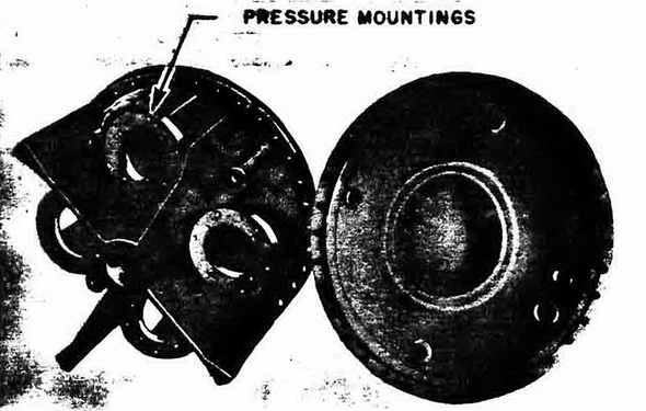
One type of experimental tail door utilizing four pressure units in combination with the M1 unit was designated 4 DM. This is shown in figure 56. |
|
|