|
|
| GERMAN UNDERWATERS ORDNANCE MINES |
| Chapter 5 - AIRCRAFT MINES - SVK |
| THE LM MINES |
|
The LMA Mine. The LMA mine was developed between 1928 and 1934, and was the first German aircraft-laid mine. Because of its relatively small (for ground mines) weight of charge, it was not used as extensively during the war as its larger counterpart the LMB. Manufacture was discontinued early in the war, and existing stocks were used up. |
|
The LMA mine existed in three models, representing progressive development. Origin-ally the mine was known as LMA, but, as the German nomenclature became more syste-matized, the earlier two models were considered LMA I and LMA II, and the most recent development was designed LMA III. These models were nearly identical, the differences lying primarily in methods of manufacture, small improvements designed to strengthen the mine case, and modification of the parachute assembly. |
|
The LMA mine could be modified easily to be suitable for surface-aircraft laying, in which case the modified assembly was designated LMA/S. |
| The LMA mineis known to have been used with the following units: |
|
1. E-BIK |
|
2. M1 (SE-BIK) |
|
3. M3 |
|
The following units, although not definitely known to have been used in LMA, could have been. |
|
1. M 1r |
6. MA 1, MA 1a |
|
2. M 1s |
MA 1r, M 1ar |
|
3. M 4 |
7. MA 2, MA 3 |
|
4. A 1 |
8. AT 1, AT 2 |
|
5. A 4 |
9. DM 1 |
|
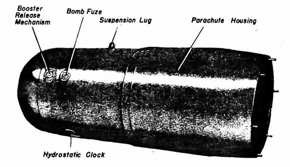
Figure 51 – LMA Mine |
|
|
|
Description of case: |
|
Shape |
Cylindrical, with hemispherical nose and tapered tail |
|
Material |
Aluminum (KSS) |
|
Diameter |
26 in. |
|
Length |
|
|
Over-all |
6 ft. 9-1/2 in. |
|
Case |
5 ft. 4-1/2 in. |
|
Parachute |
2 ft. 7-1/2 in. |
|
housing |
|
|
Tail door |
13 in. |
|
Parachute cap |
13-1/2 in. |
|
Charge |
660 lb. cast hexanite |
|
Description of External Fittings. |
|
Suspension lug |
On top center line, 24 in. abaft the nose |
|
Parachute lug |
Inside parachute housing, on center of tail door |
|
Booster release mechanism |
4 in. diameter, 270° from top center line 13-1/2 in abaft the nose, secured by keep ring |
|
Detonator
cover |
4-1/2 in. diameter, 90° from top center line, 15-1/2 in. abaft the nose, secured by keep ring. |
|
Filling-hole |
Three, 6-in. diameter, one in center of nose; two, 135° and 225° respectively from top center line, 19 in. abaft the nose, each secured by four screws |
|
Inspection
hole |
Two, 7 in. by 9 in. on top center line and 180° from top center line respectively, 12-1/2 in. from after end; each secured by four screws |
|
Parachute
release |
1/2 in. diameter on top center line, 22 in. from after end |
|
Ejecting plungers |
Six, 1/2 in. diameter equally spaced on after end |
|
|