|
|
| GERMAN UNDERWATERS ORDNANCE MINES |
| Chapter 4 - CONTACT AND MOORED INFLUENCE MINES |
| THE OMA MINES |
|
The OMA (Oberflächen Mine A) was a moored, contact, surface mine the development of which was undertaken in late 1942. It utilized a novel type of mine case and was de-signed in five models, which were designated OMA I, OMA II, OMA III, OMA IV, and OMA/ K. Of these five models only the OMA I and OMA/K were used operationally. The OMA II and OMA III were abandoned in the preliminary development stage, and the OMA IV was unperfected at the close of the war. |
|
The first moored, contact, surface mine developed by the Germans war a jury-rig aff-air designated UMA/K; it was laid in 1942. In the fall of the same year the development of a more effective mine was undertaken, this type being designated OMA I. Original re-quirements for the OMA I called for its use in water depths up to 65 feet, but these re-quirements were subsequently increased to 325 feet. The development of this mine was completed in February 1943, and it was laid in the fall of 1943. |
|
In 1944 the German Navy Department, alarmed by the large number of OMA I mines breaking loose, reduced the water-depth requirements to a mine suitable depth of 50 feet and requested an appropriate modification of the mine. The resulting modification was designated OMA/K. |
|
With the development of OMA/K the problem of preventing excessive drifters was suc-cessfully met for depths up to 50 feet. (The OMA/K, when tested in the extremely rough waters of the Elbe Estuary, lasted for more than five months.) However, since the buo-yancy of the OMA case precluded the use of a double chain mooring in depths over 50 feet, the problem remained unsolved for use in greater depths. |
|
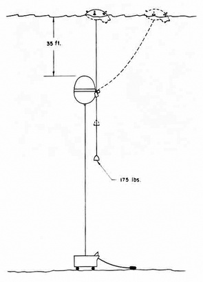
Late in 1943 the development of a moored, contact, surface mine for depths up to 985 feet was undertaken. This mine was to consists of an EMC anchor, a large steel float with a guide arrangement, an OMA Mine case with a normal spindle-type arming and dis-arming switch, and a 175-round weight. A schematic representation of the assembly is shown in Figure 31. This assembly was designated OMA IV. Because of the relative com-plexity and low priority of this mine, its development was incomplete at the close of the war. |
|
Neither the OMA I nor the OMA/K was fitted with the normal disarming devices found in moored mines. This was due to the fact that these mines had a slack mooring cable and could not be fitted with switches of the normal mooring-spindle or hydrostatic types. Therefore, since these mines broke adrift fairly often, their use created an unacceptable hazard to German shipping and shore installations. To remedy this situation the develop-ment of the OMA II and OMA III was undertaken. The OMA II was to incorrorate a me-chanical-type disarming device and the OMA III an electrical type. However, both types presented a great number of difficulties and were abandoned in the preliminary develop-ment stage. |
|
Since disarming devices of the normal type could not be applied to the OMA I and OMA/K the German Navy Department ordered that they be fitted with a ZE IVa. (60-day disarming clock). |
|
The five models of this mine utilized the same type of mine case. The characteristics of the case are as follows: |
|
Method of firing |
Chemical horns |
|
Total weights |
352 lb. |
|
Weight of charge (cast) |
66 lb. |
|
Positive buoyancy |
440 ± 22 lb. |
|
Total height |
31½ in. |
|
Diameter less skirt |
42½ in. |
|
Delay in arming |
20 - 35 minutes (Soluble washer) |
|
The significant design feature of this mine case was the steel skirt fitted to the un-derside of the case. The purpose of this skirt was to eliminate dipping of the mine. |
|
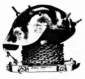
The OMA I and the OMA/K were identical except for the types of mooring and anchors used. The OMA I mooring consisted of a length of chain secured on one end to the mine case and on the other end to a length of steel cable leading from the mine anchor. The OMA/K mooring consisted of a 35-foot bight of chain secured on one end to the mine case and on the other end to a length of chain leading from the mine anchor. The an-chors were substantially the same, except that the cylindrical mine steel around which the mooring was coiled was higher on the OMA I than on the OMA/K. |
|
Figure 30 – OMA/K Mine |
|
|
|
Figure 31 – OMA IV Mine |
|
|
|
|