|
|
| BRITISH EXPLOSIVE ORDNANCE |
| Part 3 - Chapter 2 |
| High-Explosive Rockets |
|
3-in. U.P. Antiaircraft Rocket (Service) |
| Data |
| H.E. Shells | No. 1 Mk I | No. 2 Mk I |
|
Over-all length |
14 in. | 9.29 in. |
|
Diameter |
3.25 in. | 3.25 in. |
|
Total weight |
17.75 lb. | 7.6 lb. |
|
Explosive |
TNT | TNT |
|
Explosve weight |
4.28 lb. |
2.125 lb. |
|
Fuzing |
No. 700 or No. 731 |
No. 701 |
| Rocket Motors | Mk I | Mk II |
|
Over-all length |
55.19 in. | 55.19 in. |
|
Diameter |
3.25 in. | 3.25 in. |
|
Width of fins |
3.5 in. | 3.5 in. |
|
Total weight |
31.2 lb. | 31.5 lb. |
|
Propellant |
Tubular cordite | Cruciform cordite |
|
Propellant weight |
12.7 lb. | 13.0 lb. |
|
Burning time |
1.6 sec. |
2.25 sec. |
|
General: These rockets ate designed for anti-aircraft purposes, and thus are always fitted with some type of aerial-burst fuzing. |
|
Description |
|
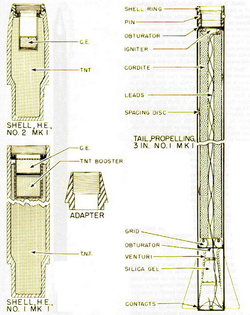
Shell, H.E., No. 1 Mk I – This shell consists of a steel cylinder, reduced in diameter at the base and threaded externally to screw into the shell ring of the rocket motor. The forward end of the shell is threaded internally to receive the base of the Fuze No. 731 or the adapter ring employed with the Fuze No. 700. Held in the nose fuze cavity by a lock-ing ring is an exploder container with a booster charge, consisting of a 26-dram C.E. pel-let and a 4-ounce TNT pellet, separated by a felt disc. A Gaine, or Booster, No. 13 Mk I is employed with fuzes used in the shell. |
|
Shell, H.E., No.2 Mk I – This shell consists of a light steel ogive struck with a 30-inch radius. The after part of the shell body is reduced in diameter and threaded externally to screw into the shell ring of the rocket motor. An internally threaded fuze adapter is wel-ded to the forward end of the shell body. A cardboard exploder container is inserted into the main explosive filler beneath the fuze adapter and contains a 12-dram C.E. booster pellet. |
|
Tail, Propelling, U. 3-in., Mks I and II – These motor are identical, except that the Mk I contains a tubular grain while the Mk II, grain is cruciform in shape. The motor body consists of a steel cylinder, slotted at the tail end to receive the four tail fins. A shell ring, fitted in the head end of the body, is internally threaded to receive the base of the shell, and has eight holes to correspond with those in the motor body. Locking pins, flan-ged on their inner ends, are inserted through these holes and are retained in poistion by two circular band springs. A copper- or cadmium-plated steel obtruator is placed in the rear of the shell ring and is separated from the propellant grain by a cardboard disc and two cardboard washers. |
|
The propellant grain is castellated at the forward end to receive the igniter, and a washer of dummy cordite, attached to the base of the grain, bears against the ring of the grid. Spacing discs and tabs are attached to the exterior of the cordite grain by a special cement. |
|
The igniter consists of a 10-gram charge of magnesium with an electric squib enclosed in a paper tube. The insulated electric leads pass through the central channel of the cor-dite grain to contacts at the after end of the motor body. |
|
The tail obturator, positioned between the grid and the venturi tube, is made in the form of a steel cup with a central perforation. The steel venturi tube is attached to the motor body by screws and welding, and contains a small bag of silica gel as a moisture-proofing measure. The leads from the igniter are connected to the four contacts around the outside of the motor body, so positioned that they make contact with the knife ed-ges on the launcher, regardless of the angle at which the rocket is loaded. |
|
Though generally fin-stabilized, these rockets are sometimes fitted with narrow ¾-in. fins, stabilization being obtained by spiralling the rails on the inside of the launcher bar-rel. |
|
Proposed new nomenclature for the rocket motors is as follows: Motor, Rocket, 3-in., No. 1 Mk I for Propelling Tail, Rocket, 3-in. Mk I, and Motor, Rocket, 3-in., No. 2 Mk I for Propelling Tail, Rocket, 3-in. Mk II. |
|
Although originally designed for use in this assembly, the H.E. Shell No. 2 Mk I has ne-ver been so employed. |
|
Remarks: The shells are painted buff over-all and carry a stencilled ring of red cors-ses ½-in. wide 1 in. behind the forward end of the shell body. A green band, upon which are stencilled in black the letters TNT, is located 4.5 in. behind the forward end of the shell. Complete indentification, filling, and manufacturing information is stencileld in black on the shell body between these painted rings. |
 |
| Figure 184 – Assembled 3-in. U.P. Antiaircraft Rocket |
 |
| Figure 185 – 3-in. U.P. Antiaircraft Rocket Components |