|
|
| BRITISH EXPLOSIVE ORDNANCE |
| Part 3 - Chapter 2 |
| High-Explosive Rockets |
|
2-in. U.P. Antiaircraft Rocket (Service) |
| Data |
| Shells | H.E. | Smoke Trace |
|
Over-all length |
5.25 in. | 5.5 in. |
|
Diameter |
2.25 in. | 2.25 in. |
|
Total weight |
2.25 lb. | |
|
Fuzes used |
No. 729 | Thermal Initiator |
|
Filling |
TNT | Smoke, P.N. 83 (M) |
|
Filling weight |
9 oz. |
5.6 oz. |
| Rocket Motor | ||
|
Over-all length |
31 in. (approx.) | |
|
Diameter |
2.25 in. | |
|
Width of fins |
2.375 in. | |
|
Total weight |
7.50 lb. | |
|
Propellant |
Tubular cordite | |
|
Propellant weight |
2.5 lb. | |
|
Burning time at 60° F. |
0.9 sec. |
|
|
General: This rocket is designed for ship-board use against in close-range attack. Be-cause of the possible danger to adjacent craft resulting from spent rounds, the H.E. shell is fitted with a self-destroying fuze. The components of the complete round include a fuzed Shell, H.E., 2-in., Mks I or II or a Shell, Smoke Trace, 2-in., Mk I, and a Propelling Tail, U. 2-in., Mks I - III, complete with fin assembly. |
|
Description |
|
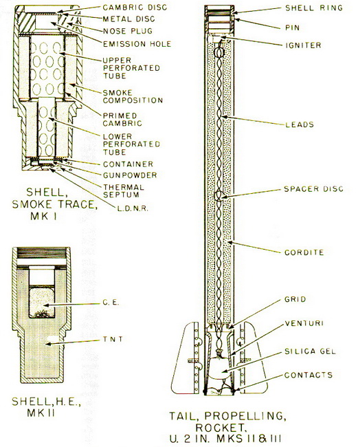
Shell, H.E., 2-in., Mks I and II – This shell is a normal H.E. type internally threaded at the nose to receive the fuze, and threaded externally at the base to screw into the shell ring of the rocket motor. The Shell Mk I, having 12 external threads per inch, will fit only the Mk I Motor. The Shell Mk II is machined with 14 external threads per inch, and will fit all other motors. The shell is painted buff over-all, with a ½-in. red band around the nose portion of the shell, and a ½-in. green band around the body. The initials of the filling are stencilled in black on the green band. |
|
Shell, Smoke Trace, 2-in., Mk I – This shell consists of an H.E. Shell Body, Mk II, mo-dified by drilling and tapping the base of the shell. A nose plug is threaded into the for-ward end of the shell and is centrally drilled to allow smoke emission. The drilled hole is closed by a thin metal disc and a cotton cambric disc. Upper and lower perforated tubes surrounded by primed cambric are separated from the nose plug by two millboard was-hers. The smoke filling is loaded around these tubes in two increments. Beneath the low-er perforated tube is located a metal container filled with 7 grains of G.20 gunpowder. |
|
The after end of the shell is closed by a threaded thermal septum of accurately ma-chined thickness, in the center of which are pressed 2½ grains of L.D.N.R. The shell is painted light green over-all, with two ½-in. red bands painted around the body. Heat from the rocket motor initiates the L.D.N.R., firing the gunpowder charge and primed cambric, which initiates the smoke composition. The gunpowder explosion also blows the discs out of the nose plug of the shell. |
|
Tail, Propelling, U. 2-in., Mks I - III – The motor consists of a welded steel cylinder, to the head of which a threaded shell ring is attached by means of spring-locked pins which engage holes in the motor body. A venturi tube is welded in the after end of the motor body. The tubular cordite grain is castellated at the forward end and rests in the motor body, supported by a metal grind at the after end. The propellant is initiated by an elec-tric igniter placed in the castellations at the forward end. The tail orifice is sealed by a cardboard, plastic, or metal closing disc, and a silica gel bag is included as a moisture-proofing measure. |
|
Electric leads from the igniter pass through the central channel of the cordite grain to the four brass contacts on the tail. These contacts, two positive and two negative, are so arranged that proper contact is maintained with the knife edges on the projector, re-gardless of the angle at which the round is loaded. |
|
The motor is generally painted white or green over-all, with identification markings stencilled on the outside. Proposed new nomenclature for the motors is as follows: Motor, Rocket, 2-in., No. 1 Mk I - III. |
|
Remarks: These rounds must not be fired outside of the temperature range of 0° and 120° F., unless filled with flashless cordite, which may be fired at temperatures between -5 and 130° F. |
 |
| Figure 182 – Assembled 2-in. U.P. Antiaircraft Rocket |
 |
| Figure 183 – 2-in. Antiaircraft Rocket Components |