|
|
| U.S. EXPLOSIVE ORDNANCE |
| PART 1 - PROJECTILES, PROPELLANT, AND PROECTILE FUZES |
| Chapter 3 - PROJECTILE FUZES |
| Section 6 - BASE FUZES FOR PROJECTILES |
|
Base Detonating Fuze Mk 13 Mods 0-7 (Obsolete) |
|
Projectiles used in |
5"/38 A.A. Common |
|
Over-all length, inches |
5.80 |
|
Diameter, inches |
Body - 1.05 |
|
|
Head - 1.26 |
|
Threaded length, inches |
1.22 |
|
Threads |
7 L.H. |
|
Material |
Body - steel Striker and housing - steel Rotor block and rotor - aluminum |
|
Arming speed, r.p.m. |
3,000 - 4,000 |
|
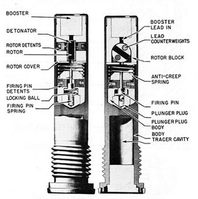
Description: This fuze consists of a one-piece body which contains two housings, the rotor housing and the firing-pin housing. The rotor housing consists of a rotor, with lead counterweights and detonator, assembled with the axis of the detonator at an angle of about 55 degrees from the axis of the fuze. The line of centers of the lead counter-weights is at an angle of about 35 degrees from the axis of the fuze. The rotor is held in this unarmed position by the two rotor detents, the tapered ends of which engage in ho-les in the side of the rotor. In this position the detonator is out of line with both the fir-ing pin and the booster. The firing-pin housing is free to move and is separated from the rotor housing by a light anti-creep spring. Contained within the housing is a firing pin which is held in position by two firing-pin detents. The point of the firing pin does not protrude from the housing in the unarmed position. Behind the firing pin is a compressed spring and a locking ball tending to throw the firing pin forward. |
|
Operation: When the projectile is fired from the gun, centrifugal force moves the fir-ing-pin detents outward against their springs, thus releasing the firing pin. When the de-tents are out, the compressed spring moves the firing pin forward and the locking ball moves into the place formerly occupied by the firing pin, thus locking it in a forward posi-tion. Centrifugal force also moves the rotor detents back against their springs, thus re-leasing the rotor. The centrifugal force, acting upon the lead counterweights in the ro-tor, causes the rotor to turn until the detonator is in line with the firing pin and booster. In this position the rotor is dynamically balanced, centrifugal force holding the two lead-filled holes at a maximum radius from the axis of rotation of the fuze. Upon impact, the firing-pin housing, being free to move, rides forward against the weak anti-creep spring, causing the firing pin to hit the detonator, which sets off the booster in the base of the fuze. |
|
Remarks: Because of an unacceptable percentage of premature functionings, these fuzes have been recalled. |
|
A cut-off Base Detonating Fuze Mk 13 is occacionally used as a tracer in B.L. & T. projectiles for target practice. |
|
Figure 106. Base Detonating Fuze Mk 13 |
|
|
|
|