|
|
| Fuzes for Rockets and Projector Charge |
| Chapter 1 |
| NOSE AND AUXILIARY DETONATING FUZES FOR SPIN STABILIZED ROCKETS |
| Section C - Fuze Mk 44 Mod 2 (Auxiliary Detonating) (Centrifugal Arming) |
| 1. General Data |
|
Used in: |
|
5.0-inch Rocket Head Mk 10 and Mk 12 (High Capacity) |
|
5.0-inch Rocket Head Mk 7 (General Purpose) |
|
Overall dimensions and weight of fuze: |
|
Length |
1.821 inches |
|
Maximum diameter |
1.5610 inches |
|
Body threads |
1.5610 inches - 20 NS - 2LH |
|
Weight |
0.50 lb. approx. |
|
Applicable specification: OS 2985 |
|
General arrangement drawing: 440406 |
|
Sketch list of drawnings & specs: 165193 |
|
Explosive components: |
|
Flash type Detonator Mk 37 (lead azide and tetryl) |
|
Lower rotor lead-in charge (tetrly) |
|
Booster lead-in charge (tetryl) |
|
Booster charge (tetrly) approximately 25 grams |
| 2. Description |
|
General. Fuze Mk 44 Mod 2 (Auxiliary Detonating) is identical with Fuze Mk 44 Mod 1 except for a modified cover disc and the inclusion of a moistureproofing sealing cover. Fuze Mk 44 Mod 2 version of this fuze was designed for use in rocket ammunition. It is essentialy a booster which houses two off-center rotors (upper and lower) carrying a detonator and a lead-in respectively which are locked out-of-line (unarmed position) by spind-held detents. Below the rotors are a fixed lead-in and a tetryl booster charge. |
|
Fuze Mk 44 Mod 2 is always used in conjuction with a nose fuze to provide additional safety and to assure detonation of the main high explosive charge in the head of the rocket. It provides additional safety because it embodies independent safety featrures, arms independently of the nose fuze, and requires a greater spin to arm than is required for the nose fuze with which it is used. The detonation train of the Fuze Mk 44 Mod 2 (after being aligned through sufficient centrifugal force) is fired by the detonator in the nose fuze. |
|
Fuze Mk 44 Mod 2 is assembled in the rocket head at the rocket loading activity. |
|
Figure 7 – Fuze Mk 44 Mod 2 (Auxiliary Detonating) (Centrifugal Arming) |
|
|
|
Use. Fuze Mk 44 Mod 2 is used in the 5.0-inch High Capacity Spin Stabilized Surface Rockets (Complete Rounds) Mk 7 Mod 2, Mk 10 Mod 0, and Mk 13 Mod 0 (see OP 1415). |
|
There were a number of rocket heads loaded during World War II with the Fuze Mk 44 Mod 0 or Mod 1. Subsequent loadings will ulitize the Fuze Mk 44 Mod 2 because of the more reliable perforance of the Fuze Mk 44 Mod 2 design. |
|
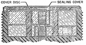
Functioning mechanism. Fuze Mk 44 Mod 2 consists of a threaded body which holds the rotor housing assembly, the booster lead-in and the booster magazine. It is closed at the forward end by a cover disc, which has a hole in the center aligned with the central flash channel of the nose fuze, and an 0.002-inch thick copper sealing cover crimped in place. Near the base end of the body there is a partition between the rotor housing as-sembly and the booster magazine. The partition has a hole in its center which receives the booster lead-in. The threaded booster magazine containing the booster charge pellet is assembled to the body and the tetryl pellet is separated from the partition by a light paper booster separating disc (washer). |
|
The rotor housing assembly consists of a die cast block with accommodation for an upper and a lower rotor, two upper and two lower torque spring loaded detents, and two rotor shafts. Both rotors are modified semi-cylindrical blocks rotating about the rotor shafts in the eccentric wells located on diagonally opposite sides of the rotor housing. Each rotor is weighted on one side and has a flat section cut out to engage a stop loca-ted in the well so that the rotation of the rotors will be restricted to align the detonator, located in the upper rotor, with the lead-in charge located in the lower rotor. Two de-tents engage two slots in each rotor to lock it in the unarmed position with the explosive elements out of line. The rotors in the unarmed position act as interrupters in blocking the central flash channel. |
|
Figure
8 – Fuze Mk 44 Mod 0 (Auxiliary Detonating), Cross Section View, |
|
|
| 3. Functioning |
|
Arming. Fuze Mk 44 arms in two stages. When the rotational velocity of the round reaches the range of 3000 to 4500 rpm, the detents are moved outward against the springs by centrifugal force and the rotors are unlocked. The rotors then rotate under centrifugal force until they meet the rotor stops. At this point the fuze is fully armed with the upper rotor detonator and the lower rotor lead-in aligned with the flash channel and the booster lead-in. |
|
Figure 9 – Fuze Mk 44 Mod 2
(Auxiliary Detonating), Partial Cross Section View, |
|
|
|
Firing. The detonator and/or relay detonator of the main fuze initiates the upper rotor detonator which in turn initiates the lead-in in the lower rotor, the booster lead-in, and the booster charge. Firing is practically instantaneous. |
|
Acceptance test data. Sample fuzes from every production lot are tested, assembled in standard service loaded projectiles with ignition fuzes or point detonating fuzes capab-le of firing the auxiliary detonating fuze and of such known performance that failure of the projectile to burst may be considered a failure of the auxiliary detonating fuze being tested. For acceptance tests all auxiliary detonating fuzes will be located on the axis of rotation of the projectile and must function as high-order detonations when initiated. Two rounds are fired at near proof pressure. At least 90% performance is required. |
|
At the discretion of the Bureau of Ordnance, ten fuzes from any lot are assembled, by means of a proper adapter, 1/8-inch off the axis to rotation of the projectie and tested as before, two rounds being fired at near proof pressure. At least 80% performance is re-quired. Failure of this test is sufficient cause for consideration by the Bureau of Ordnan-ce of the acceptability of other lots on which the off-center test was not required. In the event of any lot failing an off-center or an on-center test, twenty additional fuzes from that lot are fired in the same manner and acceptance based on the same percen-tages as before, for all thirty, i.e., 90% for the on-center and 80% for the off-center tests. |
| 4. Safety Features |
|
Detonator safety. Fuze Mk 44 Mod 2 is detonator safe.The two detents locking each rotor in the unarmed position are displaced diametrically so that they both tend to move out only under centrifugal force developed by the rotation of the round. Any force other than centrifugal force, which might unlock one set of detents would tend to hold the op-posite set of detents securely in the locked position. |
|
During shipping and stowage. Samples of fuzes from each production lot are sub-jected to rough handling tests which are considered to be more severe than conditions encountered in normal stowage and shipping. Failure of the samples to pass the tests is cause for rejection of the lot. |
| 5. Disposal and Servicing (Maintenance) |
|
General. Any dud round containing a Fuze Mk 44 (which has previously attained the prerequisite arming spin in flight) may be considered to be fully armed since the rotors do not return to the unarmed position once they have moved into the armed position. This fuze is in itself not considered to be a sensitive dud since it does not incorporate a sen-sitive primer mix or firing pin. However, the rocket nose fuze may be extremely sensitive which might render the round extremely dangerous. A dud round should be disposed of by gently lowering the round, base first, into deep water or by Explosive Ordnance Disposal Personnel in accordance with existing instructions. |
|
Disassembly. No disassembly of this fuze is permitted except by authorized activities when directed by the Bureau of Ordnance. |
| 6. Installation Instructions |
|
Rocket heads utilizing the Fuze Mk 30 and Fuze Mk 100 are shipped with the Auxiliary Detonating Fuze installed in the rocket head. |
| 7. Packing and Marking. |
|
Packing. The fuze is shipping assembled in the round. |
|
Marking. The fuze is marked with the abbreviated words Aux. Det. Fuze, the mark, mod, and lot number, the manufacturer's initials or symbol the initials or symbol of the loading facility, the month and year of loading, the anchor stamp, and the inspector's ini-tials. |
|
|