|
|
| Fuzes for Rockets and Projector Charge |
| Chapter 1 |
| NOSE AND AUXILIARY DETONATING FUZES FOR SPIN STABILIZED ROCKETS |
| Section B - Fuze Mk 100 Mod 2 (NOSE-SQ AND DELAY) (Centrifugal Arming, Point Detonating) |
| 1. General Data |
|
Used in: 5.0-inch Rocket Head Mk 7 (General Purpose) |
|
Overall dimensions and weight of fuze: |
|
Length |
4.15 inches |
|
Diameter (maximum) |
2.985 inches |
|
Body threads |
1.7000 inches - 14 NS - 1 |
|
Weight |
1.60 lb. approx. |
|
Applicable specification: (To be prepared) |
|
General arrangement drawing: 562303 |
|
Sketch list of drawnings & specs: 165472 |
|
Explosive components: |
|
A sensitive stab type Detonator Mk 25 (lead azide priming mixture and lead azide) lo-cated in the head of the fuze. |
|
A Relay Detonator Mk 49 Mod 0 (lead azide) |
|
Primer Mk 104 |
|
Black powder delay pellet |
| 2. Description |
|
General. Rocket Fuze Mk 100 Mod 2 is a centrifugal arming, impact firing, nose fuze similar in action to Fuze Mk 30 but with an extended range of useful applications. This fuze was developed by combining the Navy Point Detonating Projectile Fuze Mk 29 and the Army Artillery Fuze M48A2. (The Fuze Mk 29 and the Fuze Mk 30 are identical except for contour and length of flash tube.) The addition of the plunger assembly of the Army Fuze M48A2, containing a delay element, to the Fuze Mk 29 gives Fuze Mk 100 two fun-damental differences over Fuze Mk 30; one being the choise of either instantaneous or delay action, and the other being the added reliability inherent in the fact that the plun-ger assembly is independent in action and is always active regardless of whether instan-taneous or delay action is selected. In the event of failure upon impact of the instan-taneous feature, when set for instantaneous action, the plunger assembly will function normally and follow with a delayed detonation. |
|
Fuze Mk 100 arms when the rotational velocity of the round reaches the range of 1,500 to 2,000 rpm and will fire upon impact with any material offering sufficient resist-ance such as wood, plate, ground, or water targets. |
|
Fuze Mk 100 Mod 2 is always used in conjunction with Auxiliary Detonating Fuze Mk 44 Mod 2. |
|
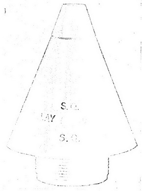
Figure 5 – Fuze Mk 100 Mod 2
(Nose-SQ and Delay), |
|
|
|
Use. Fuze Mk 100 is used in the 5.0 inch General Purpose Spin Stabilized Surface Rocket (Complete Round) Mk 7 Mod 2. (See OP 1415.) This rocket may be used effecti-vely against parked aircraft, vehicles, personnel, small buildings, light fortifications, ship-ping, etc. Since the round has limited penetration characteristics, the effectiveness is dependent on the type of action (instantaneous or delay) selected as well as the nature of the target. |
|
Functioning mechanism. Fuze Mk 100 Mod 2 is basically identical with Fuze Mk 30 Mod 3 or Mod 4 with three exceptions, namely, the addition of the plunger assembly, length of flash tube and a change in size and shape of the ogive. When the setting sleeve is set to SQ-SQ (superquick), the firing action of the Fuze Mk 100 is identical with that of the Fuze Mk 30; however, when the setting sleeve is set to DELAY-DELAY, the flash channel is blocked (as in Fuze Mk 30 when the settling sleeve is set to OFF-OFF), and the plunger assembly independently initiates the auxiliary detonating fuze after a de-lay of 0.025 seconds. The manual setting of the setting sleeve on the Fuze Mk 100 is identical with the Fuze Mk 30. However, the SQ-SQ position on the Fuze Mk 100 corres-ponds to the ON-SQ on the Fuze Mk 30 and the DELAY-DELAY position corresponds to the Fuze Mk 30 OFF-OFF position. The plunger assembly arming mechanism is completely independent of the setting sleeve position and to arm requires only the centrifugal force developed by the rotation of the round. |
|
The plunger assembly is located in a well at the base end of the fuze body and is se-cured with the bottom closing screw assembly. The plunger assembly consists of a plun-ger housing, a plunger body assembly, a plunger support, and a plunger restraining spring. The plunger housing, a light metal cup, serves as a housing for the components as well as a base for the delay firing pin. The forward end or bottom of the cup has a central flash hole, three internal punched centering tabs to serve as guides for the plun-ger support, and an off-center mounted fixed firing pin extending into the cup. The for-ward end of the plunger support rests between the three centering tabs. The plunger restraining spring fits over the plunger support and bears against the flange at the for-ward end of the plunger support. The plunger body assembly, containing the arming and explosive elements (including the delay element), mounts over the plunger support and bears against the rear end of the plunger restraining spring. An aligning pin extending from the side of the plunger rides in a small elongated guide hole in the plunger cap and serves to align the plunger with the fixed firing pin as well as to allow the plunger as-sembly to float against the plunger restraining spring. The plunger body assembly con-sists of a cylindrical brass body with a central flash hole, a threaded well to accommo-date the delay detonator assembly, a milled slot extending into the flash hole to accom-modate the centrifugal pin lock, two diametrically opposite spring loaded centrifugal plun-ger pins and a secondary relay detonator at the rear end of the flash hole. The delay de-tonator assembly which consists of the delay primer, the black powder delay pellet, and the primary relay detonator is secured in the detonator well by a threaded retaining bus-hing. A diagonal flash channel connects the primary relay detonator in the rear end of the plunger assembly. The secondary relay detonator is in line with the stab type deto-nator in the nose of the fuze. The two centrifugal pins extend partially into the central flash channel of the plunger assembly and serve to prevent the plunger from moving for-ward on the plunger support. |
|
Figure
6 – Fuze Mk 100 Mod 2 (Nose-SQ and Delay), Sectional View, |
|
|
| 3. Functioning |
|
Arming. When the rotational velocity of the round reaches the range of 1500 - 2000 rpm, which represents approximately 6 feet of travel of the round, sufficient centrifugal force is developed to move the pins out against their springs and unlock the plunger body. The centrifugal plunger pin lock rotates out and locks the centrifugal plunger pins in the outward position. The plunger restraining (anti-creep) spring prevents the plunger body from moving forward when the fuze is acted upon by deceleration such as air resis-tance or very light impacts. Upon sufficiently high impact the inertia of the plunger body overcomes the plunger restraining spring which allows the percussion primer to be inden-ted and initiated by the round-pointed firing pin. |
|
Firing. Instantaneous or superquick firing upon impact is identical with that of Fuze Mk 30. The plunger assembly also functions upon impact; however, the flash from the stab type detonator reaches the secondary relay detonator and inititiates the round (via the auxiliary detonating fuze) before the delay assembly can complete its function. Delay initiation is accomplished by blocking off the action of the stab type detonator in the nose of the fuze with the interrupter and thus allowing the plunger assembly to complete its normal delay firing cycle. |
|
Acceptance test data. The acceptance data for the superquick action of the Fuze Mk 100 Mod 2 is the same as for Fuze Mk 30. The Fuze Mk 100 Mod 2 is a modification of the previous mods to improve performance of the delay action. As of the data of the publication sufficient data had not been accumulated to relate the acceptance data and sensitivity of the fuze when set for delay action. |
| 4. Safety Features |
|
Detonator safety. The stab detonator in the head assembly is always in line, there-fore, sufficient impact on the nose of the fuze will cause crushing of the firing pin sup-port and permit the firing pin to pierce the stab type detonator. However, the fuze must be subjected to rotation in the range of 1500 to 2000 rpm in order to open the detonat-ion train. When the setting sleeve is set to SQ-SQ, the interrupter can only move out of the flash channel when sufficient centrifugal force is developed by the round's rotation. When the setting sleeve is set to the DELAY-DELAY position, the interrupter is blocked from moving out of the flash channel; however, for the delay assembly to function, the fuze must undergo sufficient rotation to enable the centrifugal plunger pins to move out and to free the plunger body from its locked position. Additional safety of the round is brought about by the use of the Fuze Mk 44 Mod 2 (Auxiliary Detonating) which has both lead-in and detonator out-of-line and requires a rotational velocity of 3000 to 4500 rpm to become fully armed. |
|
During shipping and stowage. The interrupterin the fuze is set on the DELAY-DELAY position during shipping and stowage. The centrifugal plunger pins also prevent the plun-ger body of the plunger assembly from moving forward. The relay detonators are insensi-tive to shocks encountered in handling. Fuze Mk 100 Mod 2 may be considered safe dur-ing normal shipping, stowage, and handling. |
| 5. Disposal and Servicing (Maintenance) |
|
General. (See Disposal and Servicing - General for Fuze Mk 30 for instruction pertain-ing to the observation of the closing disc on the fuze which are applicable for Fuze Mk 100 Mod 2.) If it is found that the closing disc has not been damaged and the setting sleeve is set to the DELAY-DELAY position, the fuze may be considered safe to handle, or if the closing disc is not damaged in any manner and the setting has been set to SQ-SQ position, the fuze may be rendered safe for handling by rotating the setting sleeve to the DELAY-DELAY position. |
|
Fuze Mk 100 Mod 2 is unsafe to handle after the round has been launched since the delay assembly, when once armed, remains locked in the armed position. Dud rounds should be treated with extreme caution and should be disposed of by gently lowering base first into deep water, or by Explosive Ordnance Disposal Personnel in accordance with existing instructions. |
|
Disassembly. No disassembly of this fuze is permitted except at authorized activi-ties when directed by the Bureau of Ordnance. |
| 6. Installation Instructions |
|
1. Remove the nose shipping plug from the rocket head. Inspect the interior of the rocket head nose cavity and check the threads. Clean if necessary. Be certain that the auxiliary detonating fuze is present in the rocket head. |
|
2. Remove Fuze Mk 100 Mod 2 from the container and inspect it for damage and set-ting. |
|
3. Screw the fuze into the rocket head and be certain that it seats properly. |
|
4. When packed for shipment the fuze is set DELAY-DELAY. The setting sleeve may be turned to the instantaneous position by inserting a screw driver or similar tool into the slot on the setting sleeve and turning it so that the slot aligns with the lettering SQ-SQ on the ogive. |
|
Removal from round. The fuze may be removed from the rocket head with the pro-per fuze wrench and returned to the shipping container. The closed shipping container can should in turn be sealed with adhesive tape along the broken surface. Before removal of the fuze, turn the setting sleeve to the DELAY-DELAY position. When the fuze is re-moved from the rocket head, the shipping plug and gasket must be replaced into the rocket head. |
| 7. Packing and Marking. |
|
Packing. Fuze Mk 100 Mod 2 will be shipped packed in individual hermtically sealed cans. Twenty-four individual cans are packed in a wood box 25½ inches by 16½ inches which represents a total of 1.5 cu. ft. and a total weight of 72 pounds. |
|
Marking. The words SQ-SQ and DELAY-DELAY are stamped on the plastic ogive. These markings are at right angles to each other and are placed around the hole for the setting screw with the nose end up. SQ-SQ is positioned vertically and DELAY-DELAY ho-rizonatly. The fuze is marked or stamped with the letters NF, the mark, mod, and lot number, the manufacturer's initials or symobol, the initials or symbol of the loading facil-ity, the month and year of loading, the anchor stamp, and the inspector's initials. |
|
|