|
|
| DEPTH CHARGES MARK 6 and MARK 7 |
| PART II |
| CHAPTER VI - REPAIRING AND OVERHAULING |
|
ASSEMBLY |
|
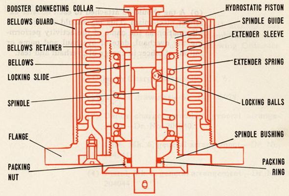
21. The method of assembling Mark 6 and Mark 6 Mod. 1 booster extenders is the same except, for the spindle bushing packing gland and seal of the Mark 6 Mod. 1. To assemble a booster extender mechanism proceed as follows: |
 |
(a) Treat all metal parts with Polar Type Rust Preventive Compound (52-C-18) Grath II. |
|
(b) Screw the extender sleeve on the spindle bushing and lock it with a spot of solder or by staking. |
|
|
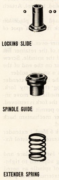
(c) Drop the locking slide into the extender sleeve and screw on the spindle guide. Try the locking for freedom of motion by rotating it and moving it up and down. |
|
|
(d) Remove the spindle guide and locking slide. |
|
|
(e) Place a small amount of vaseline on each ball and place the balls in the locking slide. Replace the locking slide with balls in the extender sleeve. |
|
|
(f) Insert the extender spring in the extender sleeve. Then place the spindle guide on the spring, press down and engage threads and screw the guide into place. Lock the guide with a spot of solder or by staking. |
|
|
(g) Now insert the extender testing tool into the hole in spindle bushing, place the assembled parts on a bench with spindle bushing end up and press down on extender testing tool until it passes completely through the spind-le guide. |
|
|
(h) The spindle bushing, extender sleeve, etc. assembly with extender testing tool inserted is now ready for combining with the carrying flange, bellows, hydrostatic piston and spindle assembly. Place a .010 inch thickness spindle bushing gasket in the carrying flange of Mark 6 Mod. 1 booster extender. Connect the end of the exten-der testing tool to the spindle and slide the spindle bushing, extender sleeve, etc. assembly into place on the spindle. |
|
| (i) Secure the spindle bushing to the carrying flange with three flat head machine screws. | |
|
(j) Insert seal around spindle and screw down gland on Mark 6 Mod. 1 pistol. Attach plain safety fork |
|
|
(k) Screw bellows guard into place on carrying flange and lock it with a spot of solder or by staking. |
|
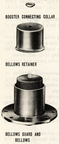 |
(l) Place bellows retainer over bellows so that the hole in the top of the retainer fits over the threaded end of the spindle. Screw booster connecting collar on the end of the spindle and lock it with a spot of solder. |
|
(m) Try the action of the booster mechanism by remov-ing the safety fork. The spindle should immediately move inward about '/4 inch when the fork is removed. If the seal is too tight to permit this on the Mark 6 Mod. 1 ex-tender mechanism back off slightly on the gland. |
|
|
(n) One percent of Mark 6 Mod. 1 extender mechanism should be tested, in pistol fixture as follows: |
|
|
(1) With plain safety fork in place and packing gland in spindle bushing adjusted to tightness suitable for free operation of spindle as noted in instruction (m) above, apply external water pressure of 20 psi. Leakage around spindle bushing gasket or into the interior of the booster extender shall not be more than 5cc after this pressure has been applied for a period of one minute. |
|
|
(2) With the travel of the hydrostatic piston and booster limited to a total of 2.0 inches from initial position, and with the safeyt fork removed, apply water pressure gra-dually until a maximum of 291 psi has been reached. No leakage should be evident during a period of one minute while this pressure is maintained. |
|
|
(3) Following the tests (1) and (2) of this instruction the booster extender mechanism shall be disassembled and all parts examined and dried. Upon reassembly, with da-maged parts replaced and functional tests as noted in paragraph 9 Chapter V performed, the mechanism will be considered satisfactory for service use. |
|
|
|
(o) A tag should be attached to each booster extender mechanism. This tag should con-tain such information as the name of the activity performing the overhaul, date of over-haul and name or initials of officer in charge of overhaul and test. |
|
|