|
|
| DEPTH CHARGES MARK 6 and MARK 7 |
| PART II |
| CHAPTER VI - REPAIRING AND OVERHAULING |
|
DISASSEMBLY |
|
20. To overhaul a booster-extender, first disassemble it, as follows: |
|
(a) Remove the bead of metal that locks the bellows guard to the booster carrying flan-ge, and unscrew and remove the bellows guard, using the strap wrench. Unscrew boos-ter connecting collar and remove bellows retainer. |
 |
(b) Test the bellows for leaks as directed in Chapter V. |
|
(c) If a soldered joint leaks, eliminate the leak by solder-ing. |
|
|
(d) If the bellows leaks, it should be replaced, following the same procedure as outlined for replacing a bellows on a pistol. |
|
|
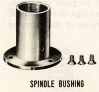
(e) Clamp the booster carrying flange in a vise and re-move the three screws which secure the spindle bushing to the carrying flange. If necessary, use a chisel to chip out the punch marks which lock the screws in place be-fore removing the screws. |
|
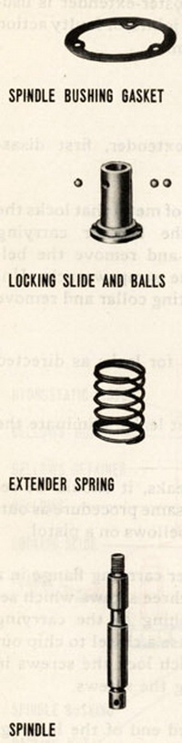 |
(f) Place the recessed end of the locking-slide tool on the booster spindle and push in. This will cause the spindle bushing to move off the carrying flange. Press in-ward on the tool and at the same time pull outward on the spindle bushing until the locking slide is completely on the locking-slide tool. Remove the slide assembly and tool from the booster-extender. Remove the spindle bushing gasket (Mark 6 Mod. 1). Pull the tool out of the slide. The slide will retract under the influence of the ex-tender spring, and the locking balls will flall out. Examine the balls and the locking-slide mechanism to see that they are in good condition. |
|
(g) To disassemble the locking-slide mechanism, break or melt the solder which locks the spindle guide to the ex-tender sleeve and unscrew the spindle guide. Remove the locking slide and spring. Remove the packing glang and seal from the spindle bushing (Mark 6 Mod. 1). |
|
|
(h) Replace or repair any part of the booster extender which is not in good condition. Refer to Ordnance Draw-ings of the booster extender for specifications of the parts of the mechanism. |
|
|