|
|
| DEPTH CHARGES MARK 6 and MARK 7 |
| PART I |
| CHAPTER II - PARTS |
| MARK 6 PISTOL |
|
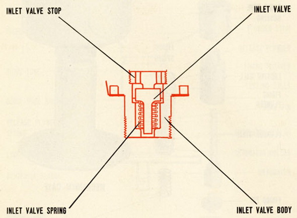
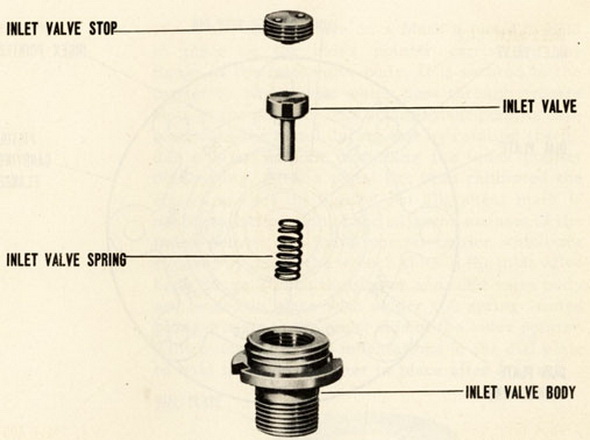
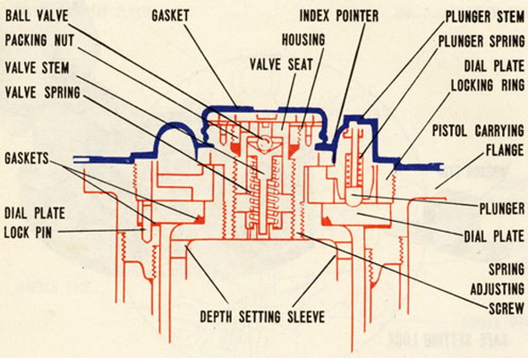
13. The inlet valve, mounted in the index pointer assembly, is a primarily an anti-coun-termining unit. It consists principally of a spring-loaded valve installed in the port through which water enters the space inside the bellows and bellows extension. In normal opera-tion the spring holds the valve clear of the seat and allows water to enter. Under abnor-mal pressure, however, such as might result from explosion of another depth charge nearby, the valve moves inward, compresses the spring, closes the port and prevents water from entering the pistol. When the pressure returns to normal the spring forces the valve open again. |
|
|
|
|
|
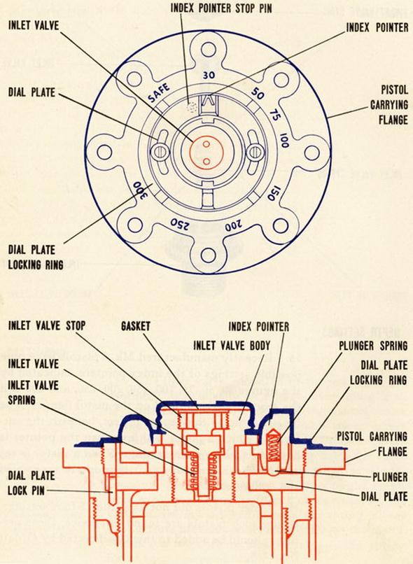
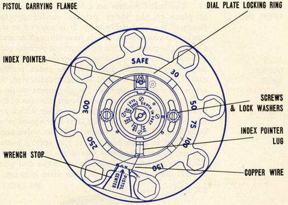
15. Recently ,anufactured Mk 6 pistols have nine possible settings of the index pointers, indicated by the figures 30, 50, 75, 100, 150, 200, 250, and 300 and the wiord SAFE stamped on the pistol flanges. The figures indicate the depths in feet, beneath the sur-face, at which a pistol will fire when the pointer is adjacent to any given setting. When a pistol is set at SAFE, it cannot fire if it is properly assembled and calibrated. |
|
16. Older pistols did not have the 75-foot settings. If any such pistols are found in ser-vice, these settings should be added to them as directed by Ordalt No. 1254. |
|
|
|
Blue indicates exterior - Red indicates interior |
|
17. The index pointer on a Mark 6 pistol is held in place on the index pointer carrier by the flange of the inlet valve body. It is secured to the carrier by two screws which pass through arcuate slots in the pointer. This arrangement permits calibration of the pistol during test by rotating the index pointer without disturbing the indes pointer dial setting. After a pistol has been calibrated the screws are set up tightly. An alignment mark is made on that portion of the adjacent surfaces of the index pointer and index pointer car-rier which are exposed by one of the wrench slots in the inlet valve body flange. (Then the screws and inlet valve body are locked in place with solder.) A spring loaded plunger is set in the under side of the index pointer. This plunger fits into indentations in the dial plate to hold the index pointer in place after it is set. |
|
|
|
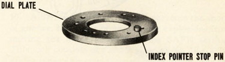
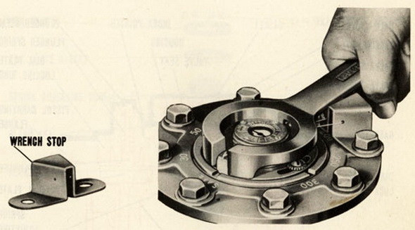
18. An index pointer stop pin is installed in the dial plate. The fucntion of this pin is to terminate the rotation of the index pointer at the 30 ft. setting on one end of the range and at SAFE on the other end. Proper depth setting of the pistol requires that the index pointer shall be turned clockwise from 30 to SAFE and counter-clockwise from SAFE to 30. The index pointer must be rotated by hand or with standard depth setting wrench. Careful observance of these instructions will prevent shearing of stop pin and consequ-ent accidental firing of detonator. |
|
|
|
As an added feature to insure proper depth setting, a wrench stop, for depth setting wrench, is attached to the pistol carrying flange by two of the eight standard case cap screws and lock washers which secure the pistol in the depth charge case. The correct location of this wrench stop is obtained by placing its attaching cap screws in the pistol carrying flange holes adjacent to the "150" and "250" dial marks. |
|
Premature or inaccurate firing of pistol may also be caused by improper assembly or cor-rosion of parts. To insure proper operations, the instructions in Chapters V and VI for testing, repairing and overhauling pistols must be followed closely. |
|
|
|
19. A SAFE SETTING LOCK prevents the shock of gunfire, bomb hits or underwater explo-sions from moving the index pointer off the SAFE setting. This lock consists of a short piece No. 19 (".0358 dia.) copper wire rove through holes in lug of index pointer and wrench stop. The ends of the wire are twisted together. The index pointer is thereby se-cured in the SAFE position and cannot be moved until wire is broken. Round nose pliers, furnished in service tool sets, are used to install the wire. It is not necessary to remove the locking wire to change the index pointer from SAFE to a praticular depth setting. The wire will be broken by the application of force to depth setting wrench handle. Whenever index pointer is reset to SAFE a new piece of wire is required. Wire, wound on spool for convenient use, is included in service tool set. Modification of pistols in service and in store to add this feature is covered by Ordalt No. 1735. |
|
|
|
Blue indicates exterior - Red indicates interior |
|
|