|
|
| DEPTH CHARGES MARK 6 and MARK 7 |
| PART I |
| CHAPTER II - PARTS |
| MARK 6 MOD. 1 PISTOL |
|
20. The Mark 6 Mod. 1 pistol differs from the Mk 6 pistol in that a spring-loaded depth-controlling valve for deep-firing is installed in place of the inlet valve assembly of the ori-ginal design. |
|
DEPTH SETTING MECHANISM - FOR DEEP FIRING |
|
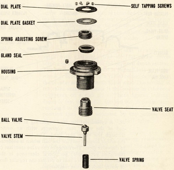
21. The depth setting mechanism for deep firing (depth controlling valve) consists of a valve body the exterior of which is identical with the inlet valve body of the Mark 6 pis-tol. The valve body has bores of different diameters from the respective inner and outer ends. The bore from the inner end is fully threaded. The bore from the outer end is threaded only part way. It supports a gland which compresses a packing against the slo-ping wall of an annular shoulder. This shoulder separates the bores and provides a stop against which the shoulder of an externally threaded portion of a valve seat is initially driven. |
|
|
|
|
|
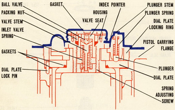
Blue indicates exterior - Red indicates interior |
|
22. A cylindrical chamber beginning at the inner end of the valve seat connects with an orifice through the valve seat head. The inner edge of the orifice forms a seat for the ball which is soldered to the valve stem. The flange of the valve stem has (a restricted yet ample) peripheral clearance in the chamber of the valve seat to permit the regular flow of water back into the mechansim. |
|
23. A spring adjusting screw has an oversize hole, the wall of which serves as a guide for the valve stem. This screw also contacts the inner end of the valve spring. The forward end of the spring engages the back of the flange on the valve stem. The spring is under compression only when the mechanism is set for depths of 350 feet or more whereupon the valve becomes seated. |
|
24. Water flows through the oversize valve stem hole in the spring adjusting screw and also through a supplementary hole in this adjusting screw. A screw driver slot is provided in the adjusting screw for adjusting spring compression by means of a screw driver during the operation of calibrating the valve. After calibration the adjusting screw is locked in place with a spot of solder. |
|
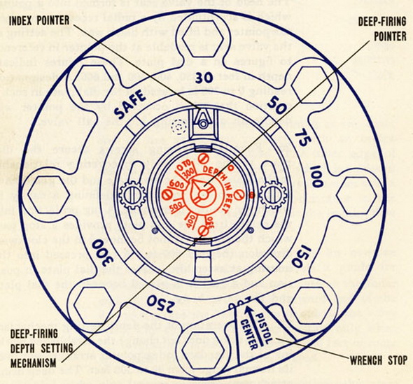
25. The head of the valve seat is also provided with a screw driver slot for screw driver setting of this member to the required depth setting. The head of the valve seat is for-ned into a pointer which is accentuated by a radial recess centered on the pointer and filled with black wax. The setting of the valve seat is readable at the pointer in reference to figures on a dial plate. These figures indicate depth in feet of 350, 400, 500 and 600. A designation reading 0 to 300 is loacted on the dial plate in such a position that when occupied by the pointer will denote an open setting for the ball valve. |
|
26. Four self tapping screws secure the dial plate to the valve body in covering relation-ship to the gland. Both the dial plate and the gland have central openings collectively defining a cavity in which the pointer is movable. A lug projecting into the cavity from the dial plate provides a stop past which the pointer cannot be moved in the clockwise direction (beyond 600 ft.) A pin, pressed into the housing at assembly, locates the dial plate in position and a gasket is placed between the dial plate and the valve body. |
|
27. The operation of the depth setting mechanism for deep firing does not change the established working of the standard index pointer arrangement over its normal range from 30 to 300 feet. The deep firing attachment assumes control only when firing is to be ac-complished in excess of 300 feet. |
|
28. The deep firing attachment lacks the anit-countermine device of the inlet valve which it replaces. However, it is belived that anti-countermining depends upon high surge impedance of the small liquid passageways rather than the inward closing of an anti-countermining valve. Therefore, the close clearance around the valve stem flange and valve stem are relied upon to prevent countermining. |
|
|
|
Blue indicates exterior - Red indicates interior |
|
MAKING A DEPTH SETTING |
|
29. When it is desired to make a pistol depth setting in excess of 300 feet the large in-dex pointer is set to 100 foot mark. Then the safety cover is removed and the setting on the deep firing attachment is made at any indexed position by less than a full clockwise turn of a screw driver inserted in the slot of the valve seat. The safety cover is replaced after the setting. The effect of turning the valve seat is to screw it away from the shoulder in the valve body. The seat thus catches up with the valve and closes the ori-fice. Since the adjustment screw is fixed the heretofore slack spring is put under com-pression in amounts proportional to the depth setting. |
|
30. Upon knocking off the knob prior to dropping the depth charge overboard, water will enter the resulting hole in the cover. A hydrostatic pressure coinciding with the depth of submergence and the index depth setting of the pointer will unseat the ball valve against the compression of the spring and water will flow into the pistol hydrostatic chamber to operate the pistol in the manner previously described. |
|
31. Gasket are installed between the dial plate the depth-setting sleeve and the flange of the Mk. 6 Mod. 1 pistol so that it may be used in depths of 350 to 600 feet without leakage into the pistol to cause premature firing. The exterior thread of the deep-firing mechanism valve body is coated with thread compound at assembly to insure water tightness at this joint. |
|
TO ELIMINATE STICKING OF THE INDEX POINTER PLUNGER |
|
32. TO ELIMINATE STICKING OF THE INDEX POINTER PLUNGER, the stem of the plunger is extended through the outside of the pointer boss. This provides a means of lubricating the stem without disassembling the pistol, and the protruding portion of the stem provi-des a means of moving the plunger within its socket to free it if it becomes stuck. |
|
LOCKING SET SCREWS |
|
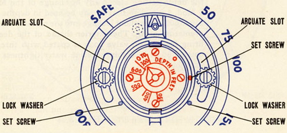
33. The use of solder for locking index pointer screws and valve body was discontinued after production got under way on the Mark 6 Mod. 1 pistol. The round head brass screws which pass through the arcuate slots of the index pointer are now fitted with in-ternal-external type lock washers. Two self-locking knurled cup point set screws are used to lock the index pointer to the index pointer carrier. One set screw of the self-loc-king type in the flange of the valve body locks this part in place. The elimination of the soldering operations expedites assembly and disassembly of the parts. It has the further advantage of removing the possibilty of damage to seals and gasket by the application of heat. |
|
|
|
Blue indicates exterior - Red indicates interior |
|
|