|
|
|
ALLIED BOMBS AND FUZES |
| BRITISH FUZES |
|
FUZE DATA |
FILE NO.: 2211.T7 |
|
NATIONALY: BRITISH |
INFORMATION DATE: October 1942 |
|
DESIGNATION |
PRINCIPAL MARKING |
No. 34 Mark I |
|
No. 34 |
CLASSIFICATION |
Mechanical Tail Impact |
|
Mark I |
TYPE OF MISSILE |
450 lb. A.P. Mark II bombs |
|
MARKINGS AND |
|
BOMBS USED IN: |
|
SUBSIDIARY |
|
This tail fuze will usually be fond in the |
|
MARKINGS: |
|
450 lb. A.P. Mark II bomb. |
|
|
|
|
DATA |
No. 34 Mark I |
|
1 |
COLOR |
|
|
2 |
OVERALL LENGTH |
|
|
3 |
OVERALL WIDTH |
|
|
4 |
MATERIAL OF CONSTRUCTON |
|
5 |
DESCRIPTION |
|
|
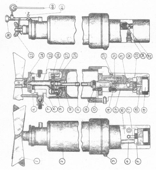
This fuze consists of an arming vane mechanism, arming spindle, and delay me-chanism. The arming mechanism consists of arming vanes (1) attached to an arm-ing spindle (25) which drives a gear train (9), (10) and (28). This gear reduction turns the arming spindle which frees the inertia pellet (30) and allows the shutter locking rod (15) to move, placing the detonator in position. |
|
|
Safety Devices:– Lead seal wire (41), whipcord becket (23) and safety pillar (39) make the fuze safe for transit. They are removed before the fuze is assembled to the bomb. The vane stop (6) and safety clip (7) keep the arming vanes from ro-tating during flight. |
|
6 |
POSITION AND METHOD OF FIXING IN BOMB |
Held in place in tail by locating pin and locking ring. |
|
7 |
FUZES LIKELY TO BE FOUND WITH |
|
|
8 |
COMPONENTS OF EXPLOSIVE TRAIN |
|
|
9 |
ARMING TIME |
|
10 |
Operation |
|
|
When the bomb is released, the arming vane is freed from the arming vane stop (6) which is attached to the safety clip (7), rotates and, working through the reduction gear, causes the arming spindle (11) to be slowly drawn towards the arming vane end to the fuze. This frees the inertia pellet (30), and also allows the shutter locking rod (15) to lift under the influence of the spring (14), thus releas-ing the shutter (33). The shutter then moves across the fuze under the action of its spring (21) until the detonator (5) is immediately over the stemmed fire chan-nel (18). The shutter is automatically locked in this position by a pawl (37), which is actuated by spring (22), the pawl in its turn being locked by a spring actuated plunger (38). This fuze is now said to be "Armed". |
|
|
They delay mechanism consists of the inertia pellet (30), creep spring (31), deto-nator (32), delay fitting (34) and powder pellet (16). The mechanism cannot func-tion until the inertia pellet has been released by rotation of the arming spindle (11). The mechanism is designed to function by the deceleration of the bomb. The arming spindle having been withdrawn, the inertia pellet remains supported only by a light creep spring. Decleration of the bomb will now cause the pellet to set for-ward onto the detonator (32), which will be pierced and fired by the needle. The flash from this detonator passes through the channel (35) to the delay fitting (34) and from there through a channel (36) filled with loose gunpowder to the pressed powder pellet (16). The flash from this pellet passes through a channel (17) to the detonator (5), which is by this time in the central position over the fire chan-nel (18). When the detonator (5) fires, it causes detonation of the magazine filling (19). |
|
11 |
Remarks |
|
|
1. Used in Bombs for attacking surface ceaft. |
|
|
2. The fuze includes a delay fitting to give one fixed period of delay only and a geared arming vane safety mechanism is incorporated to keep the fuze safe for the first 50 feet of free flight when released at an air speed of 100 m.p.h., but just to permit functioning in 300 feet at that speed. |
|
|
3. The fuze is capable of being dropped safe in an emergency. This is achieved in the usual way by releasing the bomb while the fuzing rod of the carrier is in the SAFE position. |
|
|
4. The fuze is not capable of giving direct action. |
|
|