|
|
|
ALLIED BOMBS AND FUZES |
| BRITISH FUZES |
|
FUZE DATA |
FILE NO.: 2211.N7 |
|
NATIONALY: BRITISH |
INFORMATION DATE: October 1942 |
|
DESIGNATION |
PRINCIPAL MARKING |
D.A. No. 32 Mark II* and III |
|
D.A. No. 32 |
CLASSIFICATION |
Mechanical Nose Impact |
|
Mark II * |
TYPE OF MISSILE |
A.S.-H.E. Bomb |
|
and III |
|
|
|
MARKINGS AND |
|
BOMBS USED IN: |
|
SUBSIDIARY |
|
100 lb., 250 lb. and 500 lb. A.S.-H.E. |
|
MARKINGS: |
|
Bombs Mark I, II and III. |
|
|
|
1 |
COLOR |
|
|
2 |
OVERALL LENGTH |
|
|
3 |
OVERALL WIDTH |
|
|
4 |
MATERIAL OF CONSTRUCTION |
|
5 |
DESCRITPION AND OPERATION |
|
|
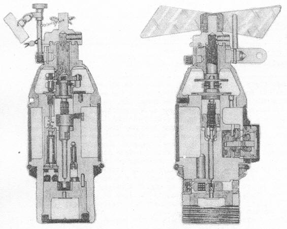
This fuze consists of a body in which is housed the arming assembly and the delay assembly. The arming assembly is fitted in the upper end of the fuze body and in-volves a system of reduction gears where in the teeth of a wheel (5) on the lower end of the arming vane spindle (16) engage with the teeth of two other wheels, (38) and (39), one of which wheels (38) is attached to the arming spindle (41). This assembly gives a ratio of 60 turns of the arming vanes (15) for one of the arming spindle (41). |
|
|
D.A. Mechanism: When the bomb is released, the arming vanes freed from the arming vane stop (19) which is attached to the safety clip (21), rotates, and working through the reduction gear described above, causes the arming nut (28) to be drawn slowly towards the nose of the fuze, the nut being prevented from rotation by the guide screw (26). This causes the striker (32), which is assembled in the base of the arming nut, to be with-drawn from the shutter (14), which then moves across the fuze under the action of its spring (34) until the main detonator (35) is immediately underneath the point of the retracted striker. The shutter is automatically locked in this position by a spring plunger (47). The fuze is now said to be armed. |
|
|
Delay Mechanism: Situated to one side of the striker is an inertia pellet (10) con-taining a small igniferous detonator (9) and until the arming nut (28), which re-tains the striker in engagement with the shutter, has been with-drawn by rotation of the arming vane spindle, the inertia pellet is definitely prevented from approa-ching the needle (7). After the fuze is armed the inertia pellet remains supported only upon a weak creep spring (8) and if the bomb is sufficiently decelerated on striking the water from a drop of 500 feet or more, or on striking a target offering slight resistance to penetrating, the inertia pellet will move relative to the rest of the fuze, and thus cause the detonator to strike the needle and fire. The flash will pass through the hole (12) in the inertia pellet and ignite the powder in the plug (13), the flash from which passes through a hole in the fuze body into the recess at the rear of the time ring (42). This ignites a pellet connected to the time ring, the composition in which will burn round until the powder pellets (29) and (30) are reached. The flame from the latter is directed upon the main detonator in the shutter which then fires, and causes detonation of the fuze magazine. This fuze can be set to function at different depths in the water by varying the angular dis-tance between the iginition pellet in the time ring and the column of pellets which ignite the main detonator. This regulates the amount of composition to be burnt between the two points, and consequently the delay interval at which the bomb will function after first striking water. The gases produced during combustion of the time composition are exhausted into the cavity (6) formed by the body sleeve (11). To seal this cavity against entry of water during taxying and whilst, immer-sed before functioning, special sealing washers (27 and 31) are inserted. |
|
|
Safety Devices: - The arming vane hus is secured against rotating in transit on the ground by a safety pillar fastened to the body of the fuze. There is cover over the delay setting device. In the carrier, the arming vanes are prevented from rotating by an arming vane stop which is attached to the safety clip. |
|
6 |
POSITION AND METHOD OF FIXING IN BOMB |
Screwed into nose of bomb and secured by means of a locking ring. |
|
7 |
Fuzes likely to be found with |
None. |
|
8 |
Components of explosive train |
|
|
9 |
Arming time |
|
10 |
Remarks |
|
|
The thickness of the wall of the steel top cap (24) is so proportioned that if a fuze fitted to a bomb is dropped from a low height and strikes a steel plate 3/8 inch or more in thickness, the detonator and so result in the detonation of the magazine (36). The cap is, how-ever strong enough to prevent the fuze functi-oning D.A. when dropped on to water from heights up to 4,000 feet. |
|
|
1. Fuzes Mark II* and III are identical in construction, the Mark II* being conver-ted Mark II fuzes. |
|
|
2. Direct action and delay mechanism are provided, and in addition a geared arm-ing vane safety mechanism, designed to keep the fuze safe for the first 50 feet of free flight when released at an air speed of 100 miles per hour, but just to permit functioning in 200 feet at that speed. |
|
|
3. The fuze is capable of being dropped safe in an emergency by releasing the bomb while the fuze control of the carrier is in the SAFE position. |
|
|