|
|
|
ALLIED BOMBS AND FUZES |
| BRITISH FUZES |
|
FUZE DATA |
FILE NO.: 2211.N6 |
|
NATIONALY: BRITISH |
INFORMATION DATE: October 1942 |
|
DESIGNATION |
PRINCIPAL MARKING |
D.A. No. 29 Mark I |
|
D.A. No. 29 |
D.A. No. 34 Mark I |
|
|
Mark I |
CLASSIFICATION |
Mechanical Nose Impact |
|
D.A. No. 34 |
TYPE OF MISSILE |
20 lb. Fragmentation and 40 lb. |
|
Mark I |
G.P.-H.E. Bombs |
|
|
MARKINGS AND |
|
BOMBS USED IN: |
|
SUBSIDIARY |
|
20 lb. Fragmentation and 40 lb. |
|
MARKINGS: |
|
G.P.-H.E. |
|
|
|
|
DATA |
D.A. No. 29 Mark I |
|
|
1 |
COLOR |
Color of the metal. |
|
|
2 |
OVERALL LENGTH |
2.46 inches (less booster) |
|
|
3 |
OVERALL WIDTH |
1.8 inches |
|
|
4 |
MATERIAL OF CONSTRUCTION |
Steel striker, brass body, aluminum cap. |
|
|
5 |
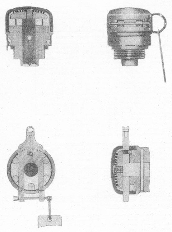
DESCRITPION |
These fuzes consist of a brass body with the standard pa-rallel nose thread. A locking device for securing it to the bomb is fitted to the body, and consists of a spring collar around the body with projections on its under side which engage in indentations in the body. When the fuze is scre- wed into the body of the bomb, this lug engages one of the holes in the face of the exploder container. A steel pressure plate is screwed to the steel striker which travels in the body of the fuze. A phosphorus bronze shear pin is fitted through the body and the striker of the fuze. Instead of being fitted with an arming vane, the pressure plate is pro-tected by a spring operated safety cap. During transit, the safety cap is retained in position by a safety fork passing underneath the pressure plate and through slots cut in the cap. |
|
|
Safety Devices: During transit on the ground, the cap is retained in position by the safety fork. If the fuze is to be used in a bomb which is carried in a container, the safety pin and fork are removed and the safety cap is then held in position by the wall of the container. If the fuze is used in a bomb which will not be carried in a container, the safety pin is removed and the fuzing wire attached to the safety fork. |
|
|
6 |
POSITION AND METHOD OF FIXING IN BOMB |
Screwed into exploder adapter tube at nose of bomb, and secured by a spring locking collar. |
|
7 |
FUZES LIKELY TO BE FOUND WITH |
None. |
|
8 |
COMPONENTS OF EXPLOSIVE TRAIN |
Has individual exploder tube at nose containing the detona-tor and exploder charge. |
|
9 |
ARMING TIME |
|
|
10 |
OPERATION |
On release from the container, the safety cap is forced away from the pressure plate by the spring and the bomb becomes armed. On impact, the pressure plate is forced inwards, shearing the shear wire, which results in the stri- ker piercing the primer cap. |
|
11 |
REMARKS |
1. These fuzes are for use in bombs which are carried in a bomb container unless instructions to the contrary are is- sued. |
|
|
2. The No. 34 Mark I is identical with the No. 29 Mark I ex- cept that an aluminum shear wire is fitted in place of a phosphorus bronze wire, and also a more robust safety cap spring is fitted. |
|
|
|
3. This fuze has no vanes. There is a spring operated alumi- num cap which fits over the pressure plate. |
|
|