|
|
| HANDBOOK OF ENEMY AMMUNITION |
| PAMPHLET No. 8 |
| GERMAN AMMUNITION FOR GUNS AND HOWITZERS AND THE TELLERMINE |
| GERMAN PULL IGNITER Z.Z. 35 |
| (Zugzünder 35) |
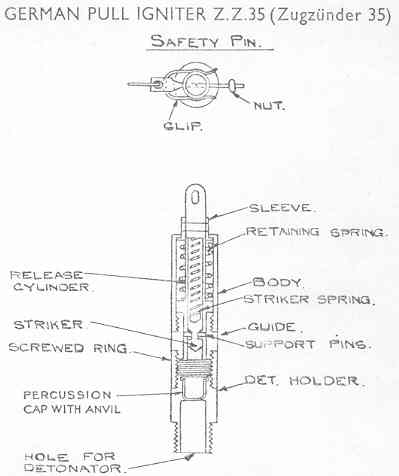
| (Fig. 3) |
|
The brass igniter, fitted with a detonator of the No. 8 type, is used with a pull wire in the side and base of the Tellermine and in conjunction with trip wires to function the S-mine. Booby traps operated by pull wires may also be fitted with this igniter. The mecha-nism consists of a striker, with spring under initial compression, held off an igniferous de-tonator by supporting pins which are held in position by a guide until the pull is applied. The body of the igniter is a cylindrical casing fitted with a projecting sleeve at the outer end and screwthreaded internally at the inner end for the insertion of the guide. The sleeve is perforated to receive the safety pin which passes through a hole in the release cylinder. The outer end of the retaining spring bears against a flange on the inner end of the sleeve. |
|
The release cylinder extends through the body and the guide and protrudes from the outer end of the body where an eyelet is formed for the attachment of the pull wire and a hole for the safety pin. A collar is formed the cylinder to support the inner end of the spiral retaining spring. The cylinder is recessed from its inner end through the greater part of its length to accommodate the striker and striker spring. Holes are formed in the cylinder wall, where it fits in the guide, to receive the pins supporting the striker. |
|
The striker is contained inside the inner end of the release cylinder and consists of a cy-lindrical body with pointed head. A recess is formed in its outer end to seat one end of the striker spring and a groove round the body to engage the supporting pins. The outer side of the groove is inclined outwards to facilitate the ejection of the pins in functio-ning. |
|
The striker spring is assembled under compression in the relase cylinder between the stri-ker and the closed end of the cylinder recess. |
|
The safety pin is fitted with a finger ring and is inserted through the sleeve and release cylinder where it is retained by a nut screwed on at the end and a spring clip which clips round the sleeve. |
|
The guide screwed into the inner end of the body and is also threaded to receive the screwed ring for the attachment of the detonator holder. The channel through the guide is a close fit round the inner end of the release cylinder to that the pins supporting the striker are held in engagement with the groove in the striker. |
|
The screwed ring is screwed on the inner end of the guide for the attachment of the de-tonator holder and acts as a distance piece between the striker and the percussion cap. |
|
The detonator holder carries a percussion cap and is bored to receive a detonator of the No. 8 type. The exterior of the holder is screwthreaded for insertion in the store with which the igniter is used. |
| Action |
|
With the safety pin removed the striker is held, against the pressure of its spring, only by support pins. When the pull wire is pulled the retaining spring is compressed and the cy-linder is drawn outwards. After moving about 0.2 inches the holes containing the support pins in the cylinder wall emerge from the guide and the pins are ejected by the inclined side of the striker groove under the pressure ofs the striker spring. The striker is then driven on to the pressure cap by its spring and the flash passes into the detonator inser-ted in the open end of the holder. |
| Fig. 3 |
|
|
|
|