![]()
![]()
![]()
![]()
|
|
| U.S.N.B.D. - ROCKETS AND FUZES |
| ROCKET HEADS |
|
|
U.S. NAVY |
|
|
|
||
|
|
5.0" ROCKET |
|
|
|
||
|
|
||
|
|
||
|
|
||
|
|
||
|
|
||
|
|
||
|
|
|
|
|
|
||
|
|
|
Spin stabilized rockets are intended primarily for shipboard use. The general purpose and Common rounds are particulary adapted for P.T. boats attacks at ranges less than 11,000 yards. The High Capacity rockets are suitable for barrage at 3,000 to 5,000 yards. |
|
The spin stabilized rockets must be used in the specially designed launchers Mk 50 Mod 0 and 1, Mk 51 Mod 0 and 1; and in launcher assemblies Mk 101 Mod 0 or Mk 102 Mod 0. |
|
TYPE |
GENERAL PURPOSE |
COMMON |
HIGH CAPACITY |
|
Head |
5.0" Mk 7 All Mods | 5.0" Mk 8 All Mods | 5.0" Mk 10 All Mods |
|
Motor |
5.0" Mk 3 All Mods | 5.0" Mk 3 All Mods | 5.0" Mk 4 All Mods |
|
Propellant Grain |
Mk 21 Mod 0 | Mk 21 Mod 0 | Mk 22 Mod 0 |
|
Igniter |
Mk 17 Mod 0 | Mk 17 Mod 0 | Mk 18 Mod 0 |
|
Length Head (Fuzed) |
10.5 in. | 7.54 in. | 18.38 in. |
|
Length Motor |
22.5 in. | 22.5 in. | 15.28 in. |
|
Overall Length (Fuzed) |
31.5 in. | 28.8 in. | 32.2 in. |
|
Weight of body |
20 lbs. | 20 lbs. | 24.6 lbs. |
|
Filler |
T.N.T. | Explosive "D" | T.N.T. |
|
Weight of Filler |
1.75 lbs. | 1.68 lbs. | 9.6 lbs. |
|
Total Weigth |
49.1 lbs. | 50.8 lbs. | 50.2 lbs. |
|
Fuzes: |
|||
|
Nose |
Mk 100 Mod 0 | None | Mk 30 Mod 0 |
|
Base |
None | Mk 31 Mod 0 | None |
|
Aux. Det. |
Mk 44 Mod 2 | None | Mk 44 Mod 1 |
|
Range (45° elev.) |
11,000 yds. | 11,000 yds. | 5,250 yds. |
|
Velocity |
1,530 ft/sec |
1,600 ft/sec |
830 ft/sec. |
|
ROCKET HEADS: |
|
5.0" Rocket Head Mk 7 (General Purpose): This head is threaded externally as the aft end to accommodate the motor. It is threaded internally at the forward end to ac-commodate the fuze adapter for rocket fuze Mk 100 Mod 0. Two spanner holes are lo-cated in the aft end of the head spaced 180° apart to facilitate assembly. The fuze adapter is internally threaded for Auxiliary Detonator Fuze Mk 44 Mod 2. The nose fuze Mk 100 Mod 0 is screwed in over the Auxiliary Detonaton Fuze. (NOTE: The fuze adap-ter and Aux. Det. Mk 44 Mod 2 are shipped installed in the head.) |
|
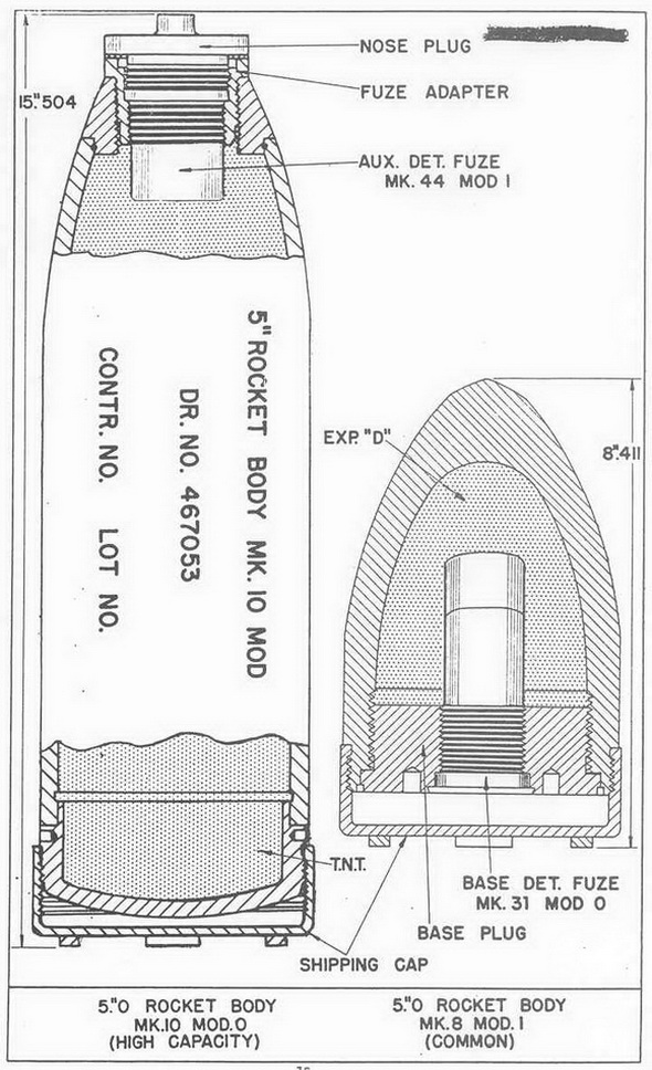
5.0" Head Mk 8 and Mods (Common): This head is internally threaded at the aft end to take base fuze Mk 31. It has two spanner holes 180° apart to facilitate assembly operations. |
|
WARNING: Do not remove the base fuze which is shipped in place in the head. |
|
5.0" Head Mk 10 and Mods (High Capacity): The nos of this head is internally threa-ded to fit nose fuze Mk 30 Mod 3 and a fuze adapter. It has two spanner holes 180° apart near the base end to facilitate assembly operations. The fuze adapter is inter-nally threaded to hold Auxiliary Detonator Fuze Mk 4 Mod 1 and the nose fuze Mk 30 Mod 3 fits over the Auxiliary Detonator. |
|
ROCKET MOTORS: |
|
5.0" Rocket Motor Mk 3 and Mods: The motor Mk 3 and Mods, as used with rocket heads Mk 7 and Mk 8 consists of the following parts: |
|
The motor tube consists of a seamless steel tube with internal threads at both ends which acts as a combustion chamber for the propellant. It is machined with a bourrelet ring at each end. The bourrelet acts as a bearing surface when fired from the tubular launcher. |
|
The shipping can is loacted in the forward end and must be removed when fitting the head to the motor. |
|
The front closure is a steel disc pressed in position near the front end of the motor tube. Its purpose is to seal the front end from moisture, dirt, etc., and also retains the igniter and propellant grain in place. A thin felt pad cushions any contact between the front closure and the igniter. |
|
The igniter Mk 17 Mod 0 consists of a flat tin use containing 35 grams of black pow-der and an electric squib. Two leads from the squib pass to the rear of the motor tube where one lead is connected to the contact rings and the other lead is grounded to the motor tube at the nozzle plate ring. |
|
A felt disc 1" thick protects the grain from accidental shock. It has an eccentrically placed hole which houses and forms a snug fit for the igniter case. |
|
The propellant is an inhibited, cruciform-shaped, extruded grain of ballistite weighing approximately ten lbs. The surface of the grain is inhibited with plastic strips to control the burning surface of the grain. |
|
The nozzle plate assembly consists of eight nozzles and a grid mounted on a nozzle plate. The cylindrical "T" shaped steel grid is pressed into place and peened in position in a center hole in the nozzle plate. It supports the propellant grain and acts as a spa-cer between the grain and the nozzle plate, creating a chamber which equalizes the pressure to all nozzles during firing. The nozzles are press fitted into the nozzle plate and are canted 12° to give a clockwise rotation. |
|
The nozzle plate ring assembly consists of a nozzle plate ring and the insulated con-tact ring. The contact ring is a steel band around the nozzle plate ring and is electri-cally insulated from it. The nozzle plate ring and contact ring are the two terminals of the igniter electrical circuit. The rings are short circuited by a short circuiting band locked around the nozzle plate ring assembly in such a manner that it creates a short circuit between the nozzle plate ring and contact ring. The short circuiting band mzst be removed when preparing the rocket for firing. |
|
The rear closure is a thin aluminum cup cemented in place at the aft end of the mo-tor and blows out after the motor pressure builds up. |
|
Note: The front and rear closure should be tempered with. |
|
The 5.0" Rocket Motor Mk 4 and Mods: The 5.0" rocket motor Mk 4 is similar to the Mk 3 discussed above except: |
|
1. The motor tube is only 13.5" longer or 7" shorter than the Motor Mk 3. |
|
2. The Mk 18 igniter is used and differs only in that it has shorter leads. |
|
3. Propellant grain Mk 22 Mod 0 is used and differs only in that it is shorter in length, and weighs approx. 5.5 lbs. |
|
4. The nozzle in the nozzle plate assembly has a smaller throat diameter. |
|
OPERATION: |
|
Electrical current to fire the rocket is fed to the motor by means of contact ring at the rear of the motor. The electrical impuls passes from the contact ring through the squib causing the squib to set off the black powder in the igniter. Burning of the igniter fills the interior of the motor tube with bot burning gas under high pressure. As soon as the propellant begins to burn, it generates a large quantity of gas and increases the pressure. A force is thus exerted in all directions blowing out the rear closure disc. The gas is then free to rush out of the nozzle end. The gas also exerts full force on the corresponding area of the closed forward end of the motor, creating a net force or thrust which drives the rocket forward. The 12° cant of the nozzle gives the rocket its clockwise rotation or spin, which is required to arm the fuzes end stabilize the rocket in flight. |
|
|
|
|
|
|