|
|
| U.S.N.B.D. - BRITISH ROCKTES AND FUZES |
| SECTION VI - ROCKET FUZES |
|
|
BRTISH ROCKET FUZE |
|
|
|
||
|
ROCKETS USED IN |
Shell, H.E. 3", No. 2 Mk I |
NO. 720 |
|
|
(Air to Air) | |
|
FUNCTIONING |
Impact instantaneous - | |
|
|
self-destroying | |
|
ARMED CONDITION |
Safety pin removed; vane | |
|
|
cup .2" above fuze head |
|
|
ARMING TIME |
5 vane revolutions |
(Service) |
|
MAX. BODY DIAMETER |
2.1 in. | |
|
VANE SPAN |
2.1 in. | |
|
OVERALL LENGTH |
2.85 in. | |
|
COLOR |
Vanes: Unpainted steel | |
| Body: Green painted alloy | ||
| Base: Bronze lacquered brass | ||
|
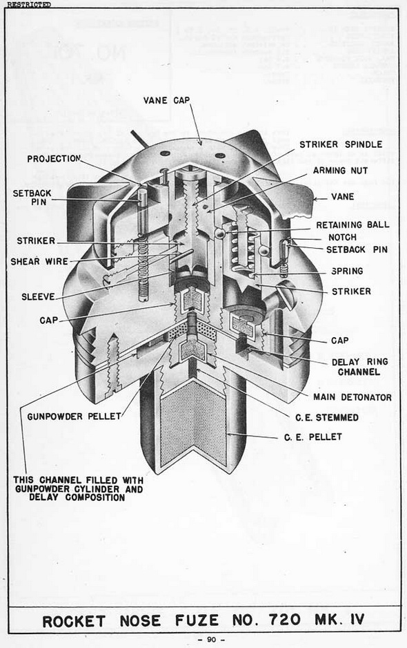
DESCRIPTION: |
|
This fuze is a direct acting impact fuze in which is incorporated a spring loaded self-destroying device designed to operate the shell in the event of a miss. The fuze is de-signed for Naval anti-aircraft purposes. |
|
The fuze consists of a metal fuze body, a vane cap, and a base piece containing the magazine, detonator, and pyrotechnic delay ring leading from the self-destroying as-sembly. |
|
Firmly fixed to the vane cap is an arming nut, into the bottom of which is screwed a threaded striker spindle. The top of the spindle is shaped to form a collar, preventing the striker from unscrewing completely from the arming nut. The other end of the spindle is fixed to the striker, which is held in the striker sleeve by a brass shear wire. Five vanes are attached to the outside of the vane cap. These vanes project into the inside of the vane cap, forming five stops, which are engaged by a setback pin. |
|
The striker sleeve is inserted into a central channel in the fuze body and is held firm-ly fixed in place by a set-screw. A safety pin passes through the top of the fuze body and the arming vane cap. |
|
Two spring-loaded setback pins located in the top of the fuze body prevent the vane cap from rotating until the rocket is fired. The first pin, located outside the vane cap, engages a notch cut in the bottom edge of the vane cap. The second, located beneath the cap, engages one of the five stops formed by the internal projections of the vanes. |
|
Offset from the center of the fuze body is a channel for the self-destroying mecha-nism, consisting of a spring-loaded striker held up by two retaining balls. The inner ball is kept engaged in a groove in the striker by the arming nut; the outer, by the vane cap. A pyrotechnic delay ring leads from the percussion cap of the self-destroying me-chanism to the main detonator. All explosive and pyrotechnic elements are located in the base piece, to which the magazine is threaded. |
|
OPERATION: |
|
The safety pin is removed manually before firing. During the acceleration period of the rocket, the two setback pins move back against their springs and disengage the vane cap, which is then allowed to rotate. As the vane cap rotates, the arming nut un-screws from the striker spindle. The vane cap and the arming nut no longer confine the retaining balls of the self-destroying device, and the balls move out, releasing the stri-ker and initiating the delay ring. The delay ring burns out and fires the detonator. |
|
If, however, the fuze makes impact with the target before the termination of the delay time of the self-destroying element, the vane cap, arming nut, and striker spindle drive the striker through the shear wire and into the detonator, initiating the shell di-rectly. |
|
REMARKS: |
|
(1) The self-destroying element is normally designed to function at an altitude of 4500 ft., but an alternative filling composition for the time rings can be provided to give self-destruction at 7500 ft. |
|
|
|
|