![]()
![]()
![]()
![]()
|
|
| U.S.N.B.D. - BRITISH LAND MINES AND FIRING DEVICES |
| FIRING DEVICES |
|
|
|
|
|
WIDTH |
5/8 in. |
BRITISH SWITCH |
|
HEIGHT |
1-1/2 in. |
COMBINATION
|
|
LENGTH |
3-1/2 in. | |
|
WEIGHT |
3-3/4 oz. (w/o cartridge) | |
|
MATERIAL |
Die cast brass and sheet | |
|
|
metal. |
(MURRAY SWITCH) |
|
OPERATING LOAD |
Pull: 10 lbs. | |
|
|
Pressure: 11 lbs. 2 oz. |
(SERVICE) |
|
|
Release: 1 lb. 4 oz. | |
|
COLOR |
Unpainted metal | |
|
|
||
|
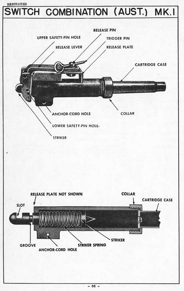
USE: |
|
This device is designed for use in anti-personnel mines and booby traps. It may be used as a pressure, pull, or release of pressure switch. |
|
INSTALLING, ARMING, & FUNCTIONING: |
|
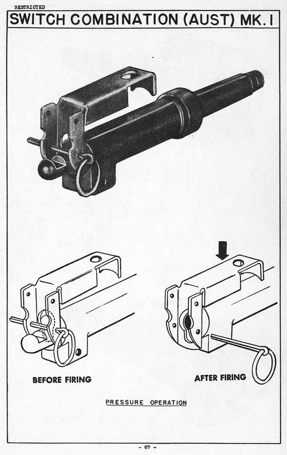
1. Pressure Operation: To install this switch for pressure operation, remove the release pin, trigger pin, and release lever. Unscrew the collar, and remove the cartrid-ge. With the blunt end of a pencil push back the striker until the narrow part of the keyhole slot in the release plate can engage in the groove in the striker. Insert the safety pin in the lower safety pin hole. Replace the collar and the cartridge case, and fit a detonator or fuze into the end of the cartridge case. Attach the switch to the charge or mine, and withdrawn the safety pin. |
|
Pressure on the release plate forces the plate toward the switch body, moving the keyhole slot downward, releasing the striker, and firing the percussion cap. |
|
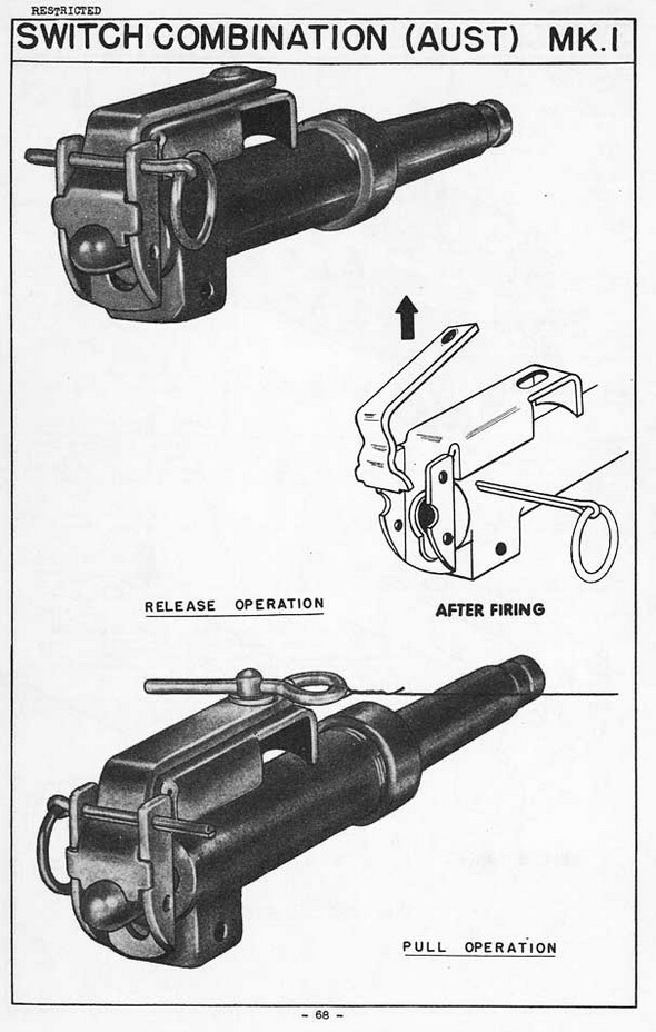
2. Pressure-release Operation: To install this switch for release operation, first set up the device as for pressure operation (above). Place the release lever in position over the release plate, and transfer the safety pin from the lower to the upper safety pin hole. Push the release lever and plate together toward the switch body until the ton-que on the release lever engages in the slot in the end of the striker. Install the device, with weight restraining the lever, connect the charge, and remove the safety pin. |
|
When the retraining load is removed from the switch, the release lever is disengaged from the slot in the striker. The freed striker, driven by its spring, then fires the percus-sion cap. |
|
3. Pull Operation: To install this switch for pull operation, first set up the device as for release operation (above). Insert release pin through holes in the release lever and plate and insert tripper pin. Attach a trip wire to a stake, tree, etc., and then to the trigger pin. Connect the switch to the charge or mine, and withdraw the safety pin. |
|
DISARMING: |
|
Insert the safety pin in the lower safety pin hole when the device is set for pressure operation; in the upper safety pin hole, when set for release or pull operation. Discon-nect the switch and the detonator from the charge or the mine, then detach the deto-nator from the switch. |
|
REMARKS: |
|
1. Prior to re-use of this switch, examine the cartridge case to see whether an un-fired cap is in place. |
|
|
|
|
|
|
|
|