![]()
![]()
![]()
![]()
|
|
| U.S.N.B.D. - BRITISH LAND MINES AND FIRING DEVICES |
| FIRING DEVICES |
|
|
|
|
|
DIAMETER |
3/8 in. |
BRITISH SWITCH |
|
LENGTH |
4-3/8 in. |
NO. 9
|
|
WEIGHT |
1 oz. | |
|
MATERIAL |
Alloy metal. | |
|
COLOR |
Aluminum. | |
|
|
Mk I |
|
|
|
||
|
|
(SERVICE) |
|
|
|
||
|
|
||
|
|
||
|
USE: |
|
This device is designed to explode a demolition charge by delayed action. |
|
DESCRIPTION: |
|
The operation of this time switch relies on the fact that Tellurium lead stretches uni-formly with time and will eventually break. |
|
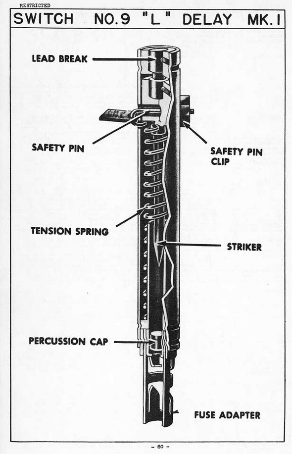
The switch consists of a tubular metal body, housing a striker, spring and lead break assembly. The lead break consists of a short lead rod grooved in the center to form a neck of reduced diameter. The upper end of the rod is pegged into a brass collar which is crimped into the top of the housing tube. The head of the striker also consists of a brass collar, and into this collar the lower end of the rod is pegged. The striker collar is an easy sliding fit in the housing tube. The lower end of the tension spring is anchored to the base of the housing tube, while the upper end is hocked over a slot in the upper end of the striker. An adapter with a percussion cap is crimped into the base of the switch. |
|
A safety pin, complete with retaining clip and label showing the delay time in days or hours, is provided to retain the striker against the tension spring. |
|
FUNCTIONING: |
|
When the safety pin is removed, the tension in the spring is taken by the lead break. The lead break stretches and eventually breaks, allowing the striker to be pulled down by the spring into the percussion cap. |
|
INSTALLING & ARMING: |
|
Refer to the temperature correction table included with each box of switches, and select the proper switch. Withdraw the safety pin, and connect the switch to the ex-plosive charge. The safety pin is of the self-locking variety, and should come away ea-sily. If the safety pin is locked in place or difficult to remove, the switch should be dis-charded. The device is in operation as soon as the safety pin is withdrawn. |
|
The switch may be connected to the explosive charge either with fuse or with a de-tonator and Cordtex. A service detonator may be crimped directly over the fuse adapter of the switch. If instantaneous or safety fuse is used, however, an adapter sleeve must first be crimped over the fuse adapter of the switch and the fuse then crimped into the adapter sleeve. |
|
DISARMING: |
|
This switch is impossible to disarm, nor can the explosive charge to which the switch is connected be defuzed safely. If necessary to defuze, cut the detonating cord or fuse connecting the switch to the explosive charge, or disconnect the switch from the charge. |
|
REMARKS: |
|
1. Two switches should be used for each important charge to guard against risk of failure. |
|
2. These switches are issued with ten different delay times, set during manufacture. The delay time at 65° F. is indicated on the tab attached to the safety pin. The timing of these delays varies considerably with changes in temperature. A temperature correc-tion table is included with each box of switches. To select the proper switch, choose the nearest timing on the temperature line to the one decided upon, and than find in that column the underlined figure. This figure gives the labelling of the delay which should be used. The degree of accuracy of the timing is stated at plus or minus 30 per-cent. However, better perforance is usually obtained, especially for timing greater than 24 hours. |
|
DEGRESS F. |
HOURS |
DAYS |
|||||||
|
35 |
3 |
16 | 32 | 64 | 8 | 19 | 38 | 76 | |
|
45 |
2 |
11 | 23 | 46 | 6 | 13 | 27 | 54 | |
|
55 |
1½ |
8 |
17 | 33 | 4 | 10 | 19 | 39 | |
|
65 |
1 |
6 |
12 | 24 | 3 |
7 |
14 | 28 | |
|
75 |
3/4 |
4 |
8 |
17 | 2 |
5 |
10 | 20 | |
|
85 |
½ |
3 |
6 |
12 |
1½ |
4 |
7 |
14 | |
|
95 |
½ |
2 |
4½ |
8 |
1 |
2½ |
5 |
10 | |
|
105 |
½ |
1½ |
3 |
6 |
|
½ |
2 |
4 |
7 |
|
|
|
|