![]()
![]()
![]()
![]()
|
|
| U.S.N.B.D. - BRITISH LAND MINES AND FIRING DEVICES |
| FIRING DEVICES |
|
|
|
|
|
WIDTH |
2.6" |
BRITISH SWITCH |
|
HEIGHT |
0.95" |
NO. 7
|
|
LENGTH |
4.0" | |
|
WEIGHT |
8 oz. | |
|
MATERIAL |
Tin | |
|
PULL OR PRESSURE |
5 - 35 lbs. (Depending on |
Mk I |
|
REQUIRED |
setting.) | |
|
COLOR |
Olive drab |
(SERVICE) |
|
|
||
|
|
||
|
|
||
|
USE: |
|
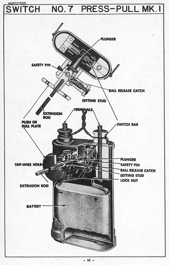
This switch is designed for booby trap installations where initiation either by pull or by pressure is desired. |
|
DESCRIPTION: |
|
This switch consists of a tin case with a bottom cap and spring to hold either a ser-vice "Battery, Dry, W, Mk I" or a standard 3-cell flat torch battery. The case is fitted internally with operating mechanism and externally on the top with two terminals for connection to the electric firing cable. The push or pull mechanism on the side of the case consists of a plunger fitted externally with a push or pull plate, and internally with a switch bar which completes the circuit when the plunger is either pushed or pulled. Two holes are drilled in the push or pull plate for the attachment of trip wire, and the plate is threaded centrally for the insertion of an extension spindle. |
|
The actuating tension or pressure is determined by the tension of the spring in the ball release catch, which is located on the side of the plunger housing. The tension of the spring is adjusted by the setting stud. The lightest actuating tension is about five lbs., and can be increased to any desired amount by screwing in the setting stud. |
|
A safety pin, with lock nut, prevents the plunger from being pulled or depressed in-advertently, and it cannot be withdrawn unless the plunger is in the dead neutral posi-tion and held so by the ball release catch. |
|
FUNCTIONING: |
|
With the safety pin removed, necessary pull or pressure on plate overcomes the pressure of the ball release catch, and the switch bar completes the circuit and fires the electric detonator to which the leads are attached. |
|
INSTALLING & ARMING: |
|
Place the mechanism either for pressure or trip wire use, then adjust the actuating pressure as required. Connect the firing leads to the terminals on the top of the case, then withdraw the safety pin. |
|
DISARMING: |
|
Remove leads from the battery terminals. Replace safety pin and remove switch and charge. |
|
REMARKS: |
|
1. To test this switch for re-use, connect to an electric detonator of the type to be used. Withdraw safety pin, and push or pull plunger which should fire the detonator. |
|
2. In December, 1943 the following instructions were issued by the Chief Engineer, Allied Force Headquarters: |
|
"This switch (No. 7) is defective, and if in possession of units will be destroyed." |
|
|
|
|