|
|
| U.S.N.B.D. - BRITISH BOMBS AND FUZES; PYROTECHNICS; DETONATORS |
| OBSOLETE BOMBS |
|
|
|
|
|
|
BRITISH |
|
|
FUZING |
Simple impact striker. |
25 LB. I.B. |
|
COLOR & MARKINGS |
Dull red overall, with two | |
|
|
½" black bands separated | |
|
|
by ½" red band painted | |
|
|
around the nose. |
Mks I & II |
|
OVERALL LENGTH |
32.6 in. |
|
|
MAX. BODY DIAMETER |
5.03 in. |
(Obsolete) |
|
TAIL LENGTH |
13.55 in. |
|
|
WT. EMPTY BOMB |
17 lbs. |
|
|
WT. FILLED BOMB |
25 lbs. |
|
|
INCENDIARY FILLING |
1 lb. Thermite, 5 lb. 4 oz. |
|
|
|
magnesium. | |
|
SUSPENSION |
Small Bomb Container, or | |
|
|
by a lug on a band from a bomb carrier | |
|
BODY CONSTRUCTION: |
|
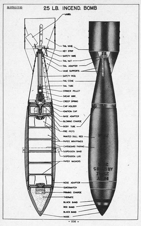
Mk I: The bomb consists of a cylindrcial steel tube secured to a hollow sharp-point-ed nose by a nose adapter (built up externally to stremline form by a cardboard fairing), a column of seven closed containers, termed fire-pots, accommodated in the body tube, a flanged base adapter which affords a mounting for a cap holder, a tail cone with a cylindrical tail vane secured to it by four vane supports, and a tail tube which accommodates a striker pellet, with a shear wire and creep spring, and a safety rod. Each of the seven fire-pots consists of a cylindrical container made of magnesium alloy and formed with a central tube which communicates, through a fire hole, with a recess in a central boss on the base of the container. The container is closed by a magnesium alloy lid which has a shallow central recess in its outer side, and holes through the lid place this recess in communication with the interior of the container. The ignition cap contains a layer of gunpowder and a layer of detonating composition. The central tube of each of the fire-pots houses a delay charge and is surrounded by a delay charge and a priming charge for the thermite and magnesium filling, which occupies the remainder of the annular chamber in the fire-pot. A loop of quickmatch extends into the bore of the central tube and has its two ends carried out through the slots in the tube and through two of the holes in the lid. An ejection charge of gunpowder is retained in the recess in a central boss of each fire-pots by a paper disc, which is secured in position by shellac. The tail cone fits over the flange of the base adapter and is held assembled to the bomb body by a tail nut which screws on to the rear end of the tail tube against a tail adapter, which fits into the rear end of the tail cone. The striker pellet has a sharp-point at the forward end and is held in the safe position by a shear wire passed through holes in the striker pellet and tail tube. The ends of the shear wire are soldered over to prevent removal. The rear end of the striker pellet receives the forward thread-ed end of the safety rod. The creep spring is housed in the forward end of the tail tube and bears against the cap holder and the striker pellet. The safety rod passes through the tail tube and is screwed into the threaded bore of the striker pellet. |
|
Mk II: Mk II has only a slight difference in the tail plate. |
|
PARACHUTE ATTCHMENT: |
|
Either of two parachute attachments are used with this bomb: No. 1, Mk I and No. 1, Mk II. No. 1 Mk I consists of a small parachute housed in a container of sheet metal consisting of a cylindrical plate and a cover. It fits lossely in the cylindrcial strut of the bomb tail. The chute is 15 in. in diameter and vented at the peak. No. 1 Mk II is similar except that it is housed in a collapsible cardboard container between cardboard pack-ing discs. |
|
STRIKER ATTACHMENT: |
|
There are two striker attachments: No. 1 Mk I, and No. 1 Mk II. No. 1 Mk I consists of a coupling fork, a snatch rod, a striker rod, a coupling socket, and a retaining sleeve which houses a spring. No. 1 Mk II is similar except that the coupling fork is fitted with a quick release pin. |
|
FUNCTIONING: |
|
With No. 1 Mk I parachute and striker: When bomb is released the cover pulls the chute out, the chute opens and pulls the snatch rod against the action of the spring until the striker rod retaining balls escape inti the annular rescess in the retaining sleeve. The striker rod then moves down against the striker pellet. On impact, the iner-tia of the rod and pellet ombine to shear the shear wire, overcome the creep spring, and pierce the ignition cap, igniting the blowing charge and blowing the base adapter and complete tail and parachute assembly from the body tube; also igniting the quick-match which passes through the lid and into the central tube of the rearmost magne-sium alloy fire-pot. The quickmatch ignites the delay charges in and around the central tube of the fire-pot, and while the surrounding priming charge, which, in turn, ignites the incendiary composition around it. Meanwhile the central delay charge burns through and fires the ejection charge in the base of the fire-pot; this has the effect of ejecting the active fire-pot from the bomb and also igniting the quickmatch of the second fire-pot, etc. Each ejected fire-pot will continue to burn for approximately 10 minutes, the magnesium alloy container and lid being consumed. Finally, the quickmatch in the lid closing the nose of the bomb, ignited the incendiary composition of the nose and pro-vides an additional fire source. |
|
With No. 1 Mk II parachute & striker: Parachute is blown out of cylindrical shroud on tail and falls apart to allow chute to open, freeing the striker mechanism. Function after this is same as that with No. 1 Mk I attachments. |
|
|
|
|