|
|
| ITALIAN AND FRENCH EXPLOSIVE ORDNANCE |
| Chapter 6 |
| ITALIAN MINES AND TRAPS |
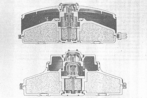
| Pignone Type I and Type II - Bakelite Anti-Tank Mines |
| Data |
|
Type I |
Type II |
||
|
Over-all diameter |
13 in. | 13 in. | |
|
Diameter of casing |
11.87 in. | 11.87 in. | |
|
Over-all height |
5.12 in. | 5.5 in. | |
|
Weight of casing |
5 lb. | 5 lb. | |
|
Type of filling |
TNT | TNT | |
|
Weight of filling |
7 lb. | 7 lb. | |
|
Activating pressure |
110 lb. | 300 lb. |
| Description |
|
Mines are constructed of moulded bakeltie; both types are of waterproof design. Metal parts in the mines when armed are: |
| 1. |
The case of the detonator, |
| 2. |
The brass striker pellet and its helical spring, |
| 3. |
The brass brush which houses the striker pellet, two steel balls, and brass shear pins. |
| 4. |
A perforated steel bar which slides to screen the striker from the detonator in the unarmed position. |
| 5. |
Brass tumblers in the igniter locking device. |
| 6. |
Nine steel helical creep springs supporting the pressure plate. |
| 7. |
In Type I, the steel wires supporting the pressure plate. |
|
Type I:The casing containing the main charge is in two halves, top and bottom being res-pectively 5/32 in. and 7/32 in. thick. They are moulded to form a central circular cham-ber for the exploder system. The top is strengthened with ribs. The two halves are as-sembled with an outer circumferential countersunk joint and an inner spigoted joint. |
|
The outer joint has rubber sealing ring and is secured by hollow plastic rivets passing through 12 pairs of lugs. The inner joint is secured by a base plug threaded into the cen-ter tube formed in the top half of the casing; this joint is sealed by a rubber gasket un-der the flange of the plug. |
|
The plug also gives access to the booster charge and detonator, placed in the central chamber closed at the top by the base of the igniter assembly. A webbing carrying hand-le is attached to the casing by wire loops which pass through the hollow rivets in two pirs of lugs. There are two filler plugs threaded into 1 1/8 in. diameter holes in the bot-tom. The holes might be adapted for anti-lifting igniters; they are diametrically opposite, approximately 2 ½ in. from the edge, but are not placed in any fixed position relative to the handle. |
|
The igniter assembly slides in the central tube formed in the top half of the casing and is retained by a locking ring. A rubber ring seals this joint. The pressure plate, 5/32 in. thick, is heavily ribbed underneath and is the full diameter of the mine casing. It rests on the top of the igniter assembly and is held in position by steel wires which are looped through four lugs, set at 90° around the mine, and fastened with two plastic rivets in-stead of one. |
|
The air space between the pressure plate and the top of the main casing is closed the circumference, by a strip of impregnated canvas fixed by two steel wires. The igniter as-sembly and arming arrangement are closed by the cap screwed into the pressure plate. |
|
Type II The main casing is similar to that of Type I. The pressure plate, ribbed on the un-derside, is only 5 ½ in. diameter; it is 3/16 in. thick. It bears on the top of the igniter as-sembly, as in Type I, but on the outside circumference is held by the ring which screws into a threaded socket, formed on the top of the main casing. The igniter assembly is sealed by two rubber rings, the latter making a joint due to the upward pressure from the helical creep springs in the igniter. |
|
A third type of bakelite mine is stated to have been produced by Pignone. It was similar to Type I, but smaller and having a 1 ½ kg charge. Because of the reduced diameter, the activating pressure was about twice the figure for Type I. It is understood that this smaller type was not produced in any quantity. |
| Igniter |
|
From the center of the base a brass tube projects upwards as a guide to the brass stri-ker pellet. A steel bar slides through the tube to act as a safety device by screening the detonator in the unarmed position; in the armed position a hole in this bar is presented to the striker pin. |
|
The striker, loaded by pressure on the helical spring, is cocked against two steel balls. The balls sit in the upper half of the striker pellet, and are retained by the sides of the cap, of tough plastic material, which slides over the brass tube. This cap is located by two brass shear pins set into the tube. It also carries a double cam-shaped collar which is free to swivel independently and control the position of the screening bar. |
|
Added safety devices are the moulded projections, which support the cam collar in the unarmed position. |
|
The position of the cam collar is controlled by an inverted tough plastic cup, slotted down the center to take the arming key of "Yale" pattern, which operates against two spring-loaded double tumblers, sliding into the spindle from the side. |
|
The key is of brass, held in a bakelite button, which is knurled at the edge and provided with an indicating nib. The nib swings between two projections on the pressure cap, marked "S" (Sicuro-Safe) and "A" (Armato-Armed). A bakelite collar fits over the head of the pressure cap and is slotted so that it is held by the projections to lock the arming key in the unarmed position. |
|
Figure 244 |
|
|
|
|