|
|
| Japanese Explosive Ordnance – Bombs, Bomb Fuzes, Land Mines,
Grenades, Firing Devices and Sabotage Devices |
| Chapter 2 – Section 2 |
| Navy Bomb Fuzes |
| B-5 (c) |
| Bombs in which used: Navy 1-kg. A/P bomb. |
| Color: Aluminum. |
| Over-all length: 2 1/4 inches (less gaine and arming stem). |
| Over-all width: 2 1/8 inches. |
| Material of construction: Aluminum alloy. |
| Position and method of fixing in bomb: Screws into base of bomb body. |
| Components of explosive train: Same gaine as in used with B-5 (b). |
| Fuzes likely to be found with: None. |
| Delay times: Instantaneous. |
|
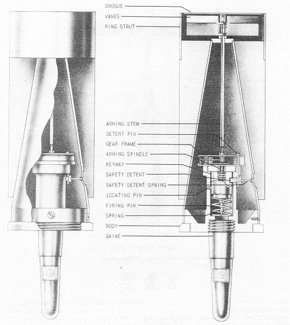
Description: The fuze is integral with the tail section, and is very similar to the B-5 (b) except for a reduction gear system used to slow down the arming process. The fuze is composed of the following parts: (1) Two small arming vanes held in the safe position by a drogue; (2) an arming stem; (3) gear frame containing the arming stem gear; interme-diate gear, pinion gear and arming spindle gear; (4) detent retaining pin; (5) spring-loa-ded safety detent; (6) arming spindle; (7) heavy inertia striker; (8) spring; and (9) fuze body. |
|
Operation: When the bomb fall free from the container, the drogue retaining the vanes is carried away by the wind, allowing the vanes to rotate. The motion of the vanes is transmitted through the reduction gear system to the spindle which is threaded out of the striker. To prevent rotation of the striker, a locating pin and keyway system are in-corporated in the fuze body and striker. As the spindle rises, it also lifts the gear frame to which is secured a pin retaining the safety detent. The safety detent, which fits through the fuze body into the striker and holds it in position, is spring-loaded outward, and removal of the safety detent pin permits it to fly out. With the spindle and detent removed, the heavy striker is held up only by a weak spring, which is overcomes on im-pact, initiating the gaine. |
|
Figure 127 – B-5 (c) Bomb Fuze. |
|
|
|
|