|
|
| Japanese Explosive Ordnance – Bombs, Bomb Fuzes, Land Mines,
Grenades, Firing Devices and Sabotage Devices |
| Chapter 2 – Section 1 |
| Army Bomb Fuzes |
| Type 1 - Aerial-Burst D-5 (a), Type 1 - Combination Fuze D-5 |
| Bombs in which used: |
|
D-5 (a) |
D-5 (b) |
|
Type 94 50- 100-kg. (and special) |
Types 1, 2 and 3. |
|
Type 3 50- 100-kg. |
Aircraft Flare. |
|
Type 92 15-kg. |
|
|
Type 99 30-kg. |
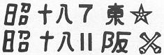
| Markings: |
|
|
|
Flare fuze (July 1943, Tokyo Army Arsenal) |
| Color: Brass. |
| Over-all length: 4 inches. |
| Over-all width: 2 inches. |
|
Material of construction: Brass except for steel firing pins, spring, spring washers, and retaining screws. |
|
Position and method of fixing bomb: Screwed into nose. |
|
Components of explosive train: Black powder magazine or high explosive gaine. |
|
Fuze likely to be found with: None. |
|
Delay times: 3 to 40 seconds. |
|
Threads: 1 5/32 inches in diameter, 13 threads per inch. |
|
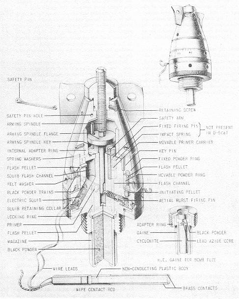
Description: The fuze body is made up of eight parts. The vane hub is secured to the upper fuze body by two retaining screws. These allow the vanes to rotate yet prevent the vanes from falling away. The upper fuze body screws onto an internal adapter ring which in turn screws around the lower fuze body. The upper powder train is fixed, being locked to the upper fuze body by a key pin. Two spring steel washers between the upper fuze body and the fixed powder train keep a working friction between the powder rings. The lower movable powder train is separated from its adjacent parts by two felt was-hers. Both the upper and lower powder train rings slip down over the lower fuze body. The squib retai-ning collar is an L-shaped ring that fits around the lower fuze body. The knurled locking ring threads on the lower fuze and serves to lock the fuze into the bomb. The magazine is filled with large grained powder and has a 3/8-inch hole through its base to allow the flash to reach the ignition charge of the flare proper. The arming spindle is 3 7/16 inches long. The upper portion is threaded for 1 3/4-inches to turn through the vane hub. At the end of the threaded portion is a 3/4-inch flange. The tip of the lower portion of the spindle is split (forked). The gas operated, aerial burst, firing pin shoulders on the forked tip of the arming spindle which denies it access to the primer until the spindle is raised (armed). In the unarmed position the arming spindle flange holds the im-pact (movable) primer carrier down and away from its fixed firing pin by bearing against the safety arm of the carrier. The 5/8-inch long electric squib fits into the lower fuze body. The 5-foot insulated single strand copper wires, and a 40-inch cord are attached. |
|
Operation: On release, the wipe contact rod is pulled through the plane's contact points, firing the squib and thus initiating the powder train rings. The vanes rotate, tur-ning the spindle up, thus freeing the striker, and the impact primer carrier. When the powder train has burned its course, the gas generated by the initiating pellet drives the firing pin forward against the creep spring and into the primer. A flash pellet relays this to the black powder magazine or gaine. If the aerial burst features fails, the primer carrier moves against the fixed firing pin on impact. |
|
Note.– The bomb fuze differs from the flare fuze in that it has a high-explosive gaine and adapter ring instead of a magazine, and the impact firing feature is left out. |
|
Figure 111 – D-5 (a) and D-5 (b) Bomb Fuzes. |
|
|
|
|