|
|
| GERMAN EXPLOSIVE ORDNANCE - PROJECTILES AND PROJECTILE FUZES |
| CHAPTER 6 |
| GERMAN PROJECTILES FUZES |
| FUZE, NOSE, MECHANICAL TIME - ZT.Z. S/30 FGL. |
|
EMPLOYMENT: Mechanical Time Nose Fuze used in 8.8-cm and 10.5-cm H.E. antiaircraft shells. (See fig. 594.) |
|
DATA: |
|
Overall length: 4.375 inches. |
|
Maximum diameter: 2.375 inches. |
|
Threaded length: 0.5 inch. |
|
Number of threads: 4 RH. |
|
CONSTRUCTION: The fuze shell resembles the Zt.Z. S/30 in external appearance but differs in the internal mechanism in which the motive power is deverid from centrifugal force instead of from a clock spring. The type is identified by the stamping "Zt.Z. S/30 Fgl" around the side of the body above the flange. The fuze is igniferous and has a maxi-mum time of running of 30 seconds. The mechanism govering the setting is designed to prevent the fuze functioning at stettings shorter than approximately 1 second. |
|
The fuze consists of the base piece or body, the cap, the screwed collar, and the me-chanism. |
|
The base piece is screw-threaded externally below the flange for insertion in the shell and has a large cylindrical recess in which the mechanism is located. The recess is screw-threaded internally for the assembly of the screwed collar retaining the cap and has a flash hole and a number of holes for the retaining bolts of the mechanism in the base. |
|
The cap is cone shaped with a rounded head and is screwed to a base ring with which it forms a groove to receive an internal rib in the screwed collar and the waved tensioning wire. The base ring carries the setting pin and the hammer spring and is secured by a fix-ing screw. The steel pin is let into the base and engages an upturned forked strip in the setting disk of the mechanism. The hammer spring is secured to the shoulder in the cap base by two screws at one end and extends diametrically across the interior of the cap. The unsupported end is forked to fit around the setting pin and is fitted with three brass hammer pieces on the underside. The two larger of these pieces are fitted one on each projection of the fork, i.e., each side of the setting pin, and the third smaller piece is nearer the center of the spring. These positions coincide respectively with the project-ions on the fork end of the strip on the setting disk and a locking pin carried in the set-ting disk. |
|
The screwed collar fitting over the lower portion of the cap is attached to the cap but is free to turn for insertion in the base piece. |
|
The mechanism is assembled in a cylindrical unit of superimposed plates of brass and alu-minum and consists of a central shaft with a spur near the lower end and a pinion at the base. The upper part of the shaft is reduced in diameter to receive the bush carrying the setting and safety disk and is screw-threaded to receive the tensioning and locking nuts. The sloping shoulder formed by the reduction of the diameter is serrated to engage with similar serrations on the bush so that the bush is locked to the shaft. The pinion at the base of the shaft is fitted with a stop pin which limits its rotation. |
|
Two eighted centrifugal toothed segments pivot near the circumference of a circular plate and each enmesh with a spur. The spurs carry pinions at their base ends which en-mesh with the spur on the central shaft. The plate carrying the centrifugal segments is cut away to provide clearance for the movement of the segments and the recesses thus forward are fitted with a spring strip which imparts the initial movement to the segment. |
|
An escapement engages the base pinion of the central shaft and is comprised of three spurs with pinions and a spur with the escapement wheel. The wheel is engaged by two vertical arms on the pallet which is weighted at each end and controlled by a straight adjustable hair spring. The pallet is locked at one end by a centrifugal safety lever which is fitted with a weighting pin and held by a retaining spring. A step formed on the pivoted end of the lever is engaged by the end of the spring strip when the lever has swung to the armed position. |
|
A disk assembly fitted at the upper end of the central shaft consists of a bush carrying two disks and a tensioning arrangement. The bush is in the form of a sleeve with a he-mispherical flange at the base. The sleeve posi tion fits over the head of the central shaft and is serrated at the lower end to engage a corresponding shoulder on the shaft. The lower of the two disks, the safety disk, is keyed to the flange of the bush and so must always turn with the central shaft. The disk is smaller in diameter than the upper disk but has a projecting leaf formed at one part of its circumference to close a slot in the upper disk and so prevent the operation of the firing mechanism. The upper disk is the setting disk and is held on the sleeve of the bush under the tension of a saucer-sha-ped spring compressed and locked by two nuts on the central shaft. Before firing, the setting disk can be rotated relative to the bush and safety disk, but after firing, the disks are locked together when the locking pin carried in the setting disk is driven into the safety disk by the hammer spring. The setting disk has an upturned forked strip which engages the setting pin in the cap and, diametrically opposite, a curved slot which when alined with a projection of the firing arm releases the firing mechanism. |
|
The firing arm, operated by centrifugal force, consists of a shaft with a flat formed by a recess near it lower end and with a cross head at its upper end. The cross head has a weight attached to the underside at the end of one arm and a vertical strip projecting upwards from the end of the other arm. The strip bears against the edge of the setting disk and the lower end of the shaft obstructs the rotation of the retaining bolt. |
|
The retaining bolt securing the retaining catch in contact with the detonator pellet is a centrifugal device held in the safe position by the shaft of the firing arm. The bolt con-sists of a short shaft with a radial arm attached at the head and a flat formed near the base. The radial arm engages the firing arm and provides the weight for centrifugal ac-tion whilst the flat engages the end of the flat side of the retaining catch. |
|
The retaining catch in the form of a hook is pivoted at one end and hooked to engage the detonator pellet ar the other. |
|
The detonator pellet contained in a transverse rectangular slot in the base of the me-chanism unit is of brass and is rectangular in shape. A notch is cut in the two vertical sides and the detonator is contained in a recess at the inner end. A flash channel from this recess emerges at the underside of the pellet. A curved spring strip between the outer end of the pellet and one end of the pellet slot is held under compression by the retaining catch engaging in one of the side recesses of the pellet. The striker is fixed in the opposite end of the slot. The detonator pellet is also held by a centrifugal safety catch. |
|
The safety catch, located in a channel cut in the side of the pellet slot, consists of a flat brass plate shaped at its inner end to engage the front end and one side of the de-tonator pellet. The catch is retained in the safe position by a spring-loaded plunger with a rounded base which enters a recess in its surface. |
|
ACTION: The time of running is governed by the size of the arc extending clockwise bet-ween the curved slot in the setting disk and the position of the vertical projection on the cross head of the firing arm. |
|
The fuze is set by turning the cap with the aid of a setting device. The rotation of the cap is transmitted to the setting disk by the setting pin engaging in the forked strip of the setting disk whilst the safety disk is held keyed to the stationary bush on the central shaft. The curved slot in the setting disk is thus rotated clear of the projecting leaf on the safety disk. The width of the leaf and its position relative to the vertical projection on the firing arm are so arranged that the leaf still closes the slot at settings up to ap-proximately 1 second and sp prevents the fuze functioning dangerously near the gun. |
|
On acceleration, the hammer spring sets back, flattening permanently the forked strip on the setting disk and thus disengaging it from the setting pin. At the same time, the ham-mer spring strikes the small locking pin and drives it into an unsupported part of the safe-ty disk. The setting disk is then locked to the safety disk. When the safety lever has been thrown clear of the pallet by centrifugal force, it is retained in this position by its spring engaging a step at its outer end. The toothed segments, operated initially by the springs fitted in the plate and subsequently by centrifugal force, then revolve the central shaft by means of the spur, and pinions. The disk assembly rotates with the shaft, the rate of rotation being controlled by the escapement. Whilst this movement is in progress, the weighted end of the cross head on the firing arm is tending to swing outwards but is prevented from so doing by the upturned end bearing against the edge of the rotating disk. Also, the spring-loaded plunger of the safety catch is eased from the catch by de-celeration and the catch is thrown clear of the detonator pellet by centrifugal force. |
|
When the slot in the setting disk reaches alinement with the upturned end of the cross head, the firing arm is revolved to the extent permitted by the slot and the recess cut in its lower part is turned to provide clearance for the arm of the retaining bolt. The arm then moves outwards and the flat surface on its shaft is rotated through a right angle so that it clears the side and the curved end of the retaining catch. The catch is then thrown clear of the detonator pellet which is driven onto the striker by its spring. |
|
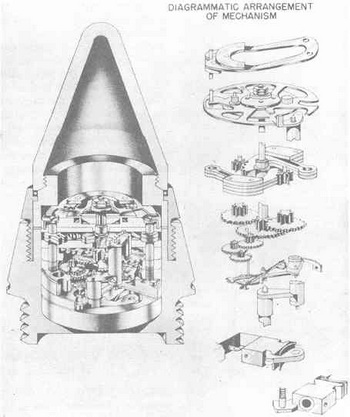
Figure 594 – Zt.Z. S/30 Fgl. |
|
|
|
|