|
|
| GERMAN EXPLOSIVE ORDNANCE - BOMBS, BOMB FUZES, ROCKET, LAND MINES, GRENADES AND IGNITER |
| Chapter 4 |
| GERMAN LANDMINES, GRENADES, AND IGNITERS |
| T.Mi.Z. 35 (PRESSURE TYPE) |
| DATA: |
| Length 2 1/4 inches. |
| Diameter: 1 5/8 inches O.D. |
| Pull or pressure required: 250 to 400 pounds. |
| Material: Brass. |
|
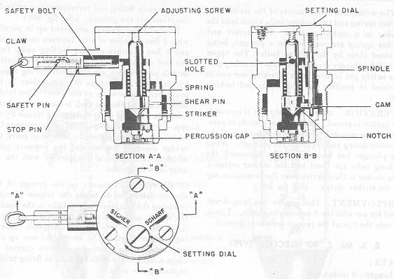
DESCRIPTION. The body is generally made of brass and houses a cylindrical-shaped assembly which has a free fit in the igniter body. The collar screws to the bottom of the body to hold the cylindrical assembly in place in the body. Clearance is provided so that the body and the internal cylindrical assembly can move vertically with respect to each other, except as prevented by the safety devices, to be described later, and the shear pin. The internal cylindrical assembly consists of a body which acts as a guide for the striker or firing pin and a base plug, containing the percussion cap. When igniter safety devices are disengaged, the striker is held in a cocked position within the guide body by the striker spring un-der compression and the shear pin. A cover plate is fastened by screws to the top of the igniter body and contains a setting dial. The plan of the igniter shows marking "SICHER" (safe), "SCHARF" (armed), and a red dot on the setting dial. A white line appears under "SICHER" (safe) and a red line appears under "SCHARF" (armed). A slot is provided on the setting dial to permite turning. (See fig. 269). |
|
The igniter has two safety devices. The main safety device consists of a safety bolt which passes through a slotted hole in the striker and prevents full movement of the striker pin if, for instance, the shear pin should be damaged or sheared, and locks move-ment between the body and the cylindrical body. The safety bolt is moved in or out of the "safe" position by means of a claw to which is attached a flexible wire. A stop pin in the body prevents the complete removal of the safety bolt The claw and wire are remo-vable and will probably be missing in captured mines when found in armed condition. The cylindrical bolt is designed with a shoulder to center it in the hole in the igniter body. The enlarged portion of the bolt is slotted to receive the claw, which is engaged by the pin. The secondary safety device is designed to hold the striker off the shear pin until the ig-niter is armed. The secondary safety device is a spindle with its upper end secured to the setting dial in the cover plate of the igniter. The spindle's lower end has attached to it a cam. The cam is equivalent to a 130° sector of a spiral ramp. The device is in a "safe" position when the red dot on the setting dial is opposits the white line under the word "SICHER" (safe). In this position the cam fits underneath a notch cut into the shoulder of the striker. The device is armed, except the bolt, by turning the setting dial counterclockwise until the red spot is opposite the red line under "SCHARF" (armed). This operation rotates the cam to clear the notch of the striker, thus releasing the striker un-til it is supported only by the shear pin. In this position the full compression of the spring is resisted only by the shear pin. |
|
OPERATION. This igniter is armed by turning the setting dial counterclock-wise until the red spot is opposite the red line under "SCHARF" and then withdrawing the safety bolt until it is latched by the stop pin. After arming, sufficient pressure applied at any point on the lid of the mine will move the igniter bofy downward in releation to the internal firing assembly. When the body reaches a point where the top of the striker has made contact with the adjusting screw, further down-ward movement will force the striker downward, thus shearing the shear pin. The compressed striker spring will then force the striker into the percussion cap, firing it. |
|
EMPLOYMENT. This igniter was especially designed for use as the main igniter in the Tellermine. |
| REMARKS. This igniter is subject to blast effect. |
|
Figure 269 – T.Mi.Z. 35 Pressure Igniter |
|
|
|
|