|
|
| GERMAN EXPLOSIVE ORDNANCE - BOMBS, BOMB FUZES, ROCKET, LAND MINES, GRENADES AND IGNITER |
| Chapter 3 |
| GERMAN ROCKETS |
| 8.8-cm HOLLOW CHARGE ROCKET, FIN STABILIZED |
| DATA: |
|
Nature of projectile: Multiple-venting, non-rotating, fin stabilized pusher motor. |
| Caliber: 8.87 cm. |
| Over-all length (complete round): 19.4 inches. |
|
Total weight (complete round): 5 pounds, 13.6 ounces. |
| Nature of fuze: Instantaneous nose percussion. |
| Nature of filling: Cyclotol. |
| H.E. Head: |
|
General shape: Cylindrical main body; truncated, conical impact cap and rear section. |
|
Dimensions: |
|
Over-all length: 10.47 inches. |
|
Main body: 0.045 inch. |
|
Forward Diameter, Impact Cap: 1.356 in. |
|
Weights: |
|
Empty: 4 pounds 0.75 ounces. |
|
Markings: |
|
Cylindrical Portion of Body: |
|
Stenciled in purple: WaA 424. |
|
Rear Portion of Body: Stenciled in white: 43 fcc 47. |
|
Fuze: Either A.Z. 5095 or A.Z. 5095/1 instantaneous nose percussion fuzes. |
|
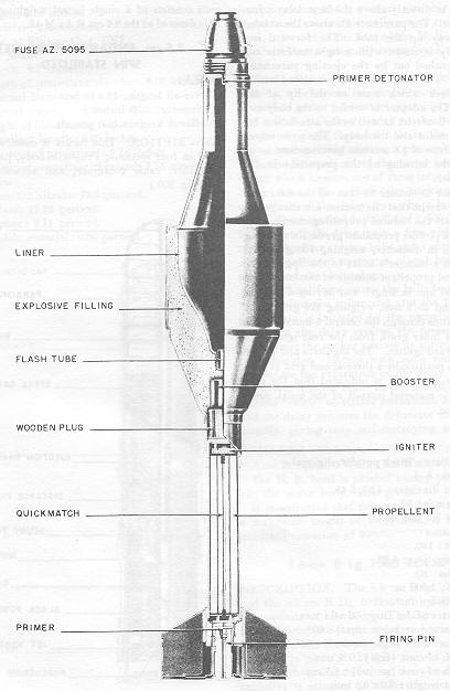
DESCRIPTION. This projectile is fired from the mobile antitank rocket launcher 8.8 cm Raketenwerfer and is similar in appearance to the 8.8 cm Raketen Panzerbüchse Granate 4322. The projectile, which is fin-stabilized, consists basically of an H.E. head, a motor tube, and a tail-fin assembly. (See fig. 210.) |
|
H.E. Head. The head of the projectile consists of the body containing the cyclotol hollow-charge located by a cavity liner and an impact cap. The impact cap is flanged at the rear end to bear against the cavity liner and is fitted at the forward end with an adapter, threaded to receive either two nose percussion fuzes, the A.Z. 5095 or the A.Z. 5095/1. |
|
Two pressed flanges at the forward end of the body secure the impact cap and the ca-vity liner. The rear end of the body is conical in shape and fits over a tail adapter which forms the junction with the motor tube. A reinforcing sleeve is pressed into position over the cylindrical portion of the body and provides the forward bearing surface of the pro-jectile. |
|
At the lower end of the cavity liner is a flash tube below which is located the gaine; this consists of an aluminum cap containing a charge of PETN and wax and a detonator. The gaine is separated from the motor tube by a wooden plug which acts as a buffer and which also provides the necessary thermal insulation between the motor and the gaine. |
|
Motor Tube. The forward end of the motor tube is sealed and threaded to screw into the tail adapter. The rear is screwed into the venturi block. |
|
The propellant consists of a single stick with 14 small longitudial perforations and a single axial drilling of larger diameter. Three lands around the outside of the stick keep the pro-pellant from touching the inside of the tube and ensure an external burning surface. Two grids, one at each end, are used to support the propellant; each grid is a triangular metal platform on three legs. At the rear there is a wire mesh between the grid and the propel-lant to prevent any unburnt particles from blocking the venturi drillings. |
|
Between the grid and the propellant at the forward end is an ignition charge mounted so that it is free to burn on both surfaces. A celluloid tube, containing a thin strip of what appears to be nitrocellulose powder, is located in the axial drilling of the propellant; both ends of the tube are capped with a block of black powder. This trains serves to transmit the flash from the primer to the ignition charge at the forward end of the motor tube. |
|
Tail-Fin Assembly. The tail-fin assembly consists of a venturi block, stabilizing fins, obtu-rator, and percussion igniter. |
|
The venturi block, which is screwed over the end of the motor tube, has six venturi dril-lings parallel to the axis of the projectile. These are each formed by two drillings of diffe-rent diameter; instead of taper there is a sudden step from the smaller to the larger dia-meter. The block is drilled and tapped in the center to receive the firing-pin adapter. A collar in the rear of the firing-pin adapter holds the obturator in position around the rear of the fin assembly. A percussion cap is mounted in the forward end of the firing-pin adapter, immediately in rear of the quickmatch train. The adapter is machined down to a separation point near the rear end; when the projectile is fired, the adapter severs, and the rear portion remains in the breech together with the obturator. |
|
The six stabilizing fins are mounted in three pairs around the venturi block and are strengthened by a sleeve fitted around the fins and under the forward lip of the obtu-rator. |
| REMARKS. 1. The German designation for this round is "8.8 cm R.Pz.B.Gr." |
|
2. This same round, modified for percussion firing, is used in a single tube, two-wheel launcher, the "8.8 cm Raketenwerfer 43". |
|
Figure 210 – 8.8-cm Hollow Charge Antitank Rocket |
|
|
|
|