|
|
| GERMAN EXPLOSIVE ORDNANCE - BOMBS, BOMB FUZES, ROCKET, LAND MINES, GRENADES AND IGNITER |
| Chapter 2 |
| GERMAN FUZES |
| DUST FUZE FOR GERMAN SD 10 BOMB |
|
DESCRIPTION. The principle of charging a condenser electrostatically by means of a dust field was developed several years ago by the electrical fuze laboratory of Rheinme-tall Borsig. It was decided early in 1943 to incorporate such a principle into fuzes for the projectiles and small bombs. |
|
The original tests on the feasibility of dust type arming fuzes for small bombs were car-ried out using the EI 224.02 37-mm. projectile fuze especially adapted for the SD 4 anti-personnel bomb. The test data resulting from the use of this equipment proved to be very inadequate. |
|
In order to further develop this principle for use in bombs, an impact nose fuze was de-veloped for the SD 10 antipersonnel bomb which incorporated a larger static generator than which has previously been used. |
|
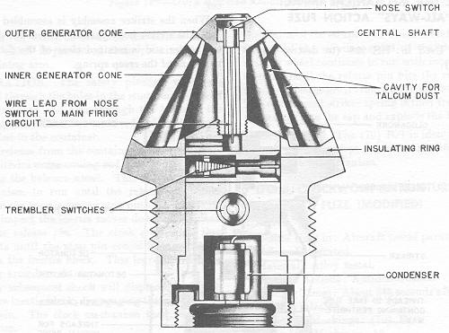
This fuze was so designed that the static generator necessary for creating the required electrical charge could be installed in the base of the old A.Z. C 10 mechanical impact fuze. For the sake of simplicity this fuze can be divided into two main parts: A – the up-per half which consists of the static generator and one impact switch, and B – the lower half which consists of the body of the fuze. A plexiglas insulating ring separates the sta-tic generator from the main body of the fuze. (See figs. 191A and 191B.) |
| The constituent components for each parts are as follows: |
| A. | Upper part (static generator): |
| 1. | Central shaft. | |
| 1a. | Nose impact switch. | |
| 2. | Outer generator cone. | |
| 3. | Inner generator cone. | |
| 4. | Plexiglas insulating ring. |
| A. | Lower half (fuze body): |
| 1. | Fuze body. | |
| 2. | Plastic circuit housing. | |
| 2a. | Tumbler switches. | |
| 2b. | Condenser. | |
| 3. | Squib. | |
| 4. | Tracer cap. | |
| 5. | Tracer cap cover. |
|
The central shaft performs two functions. Its primary function is to hold the static gene-rator together. This is accomplished by threading the lower end of the shaft into the plastic housing within the fuze body itself. By this means the two generating cones are forced down on the insulating ring and held fast. The secondary function of the shaft is to house one impact switch of the firing circuit and the insulated tube for the electric lead to the switch. |
|
Figure 191A – Dust Fuze for SD 10 Bomb |
|
|
| The over-all dimensions of the fuze are as follows: |
| Height: 4 inches. |
| Diameter: 2.7 inches. |
|
The over-all height does not include the gaine or booster which normally threads into the base of the fuze. |
| The outer generator cone dimensions are as follows: |
| Over-all height: 1 1/2 inches. |
| Outside diameter at base: 2 9/16 inches. |
| Outside diameter at top: 1 5/16 inches. |
| Over-all thickness of cone wall: 7/32 inch. |
| Number of slits: 17 or 19. |
| Length of slits: 1 1/2 inches approximately. |
| Width of slits: 1/32 inch. |
| The inner generator cone dimensions are as follows: |
| Over-all height: 1 3/8 inches. |
| Outside diameter at base: 1 11/16 inches. |
| Outside diameter at top: 3/4 inch. |
| Over-all thickness of cone wall: 3/32 inch. |
| Number of slits: 13 to 15. |
| Length of slits: 1 1/16 inch approximately. |
| Width of slits: 1/32 inch. |
| The insulation dimensions are as follows: |
| Outside diameter: 2 23/32 inches. |
| Inside diameter: 1 3/16 inches. |
| General thickness: 3/32 inch. |
| Built-up thickness at outside perimeter: 7/32 inch. |
|
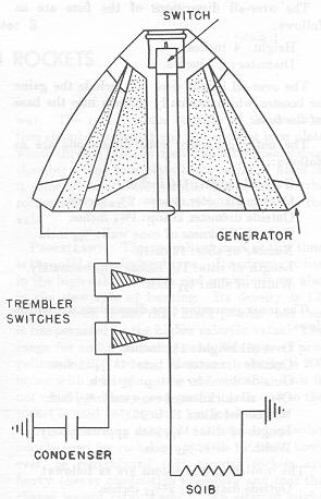
The firing circuit is set up along the lines of all standard fuze firing circuits. The genera-tor is connected to the condenser by a wire lead which runs up through the plastic housing, across the upper side of the plexiglas insulating ring and makes contact with the outer generating cone. The other lead from the condenser is grounded to the lower fuze body. A lead from the nose switch is connected in series with the two spring type tremb-ler switches and also the squib and then grounded. |
|
OPERATION. The plastic cap covering the slits on the head of the fuze is removed just before the bombs are dropped. As the bombs fall free, the air stream enters the fuze via the slits in the outer generating cone. This action disturbs the talcum dust and creats a dust screen in and aorund the forward part of the fuze. |
|
The electrostatic charge is developed when the dust particles come into violent contact with each other and with the two generator cones. The condenser is connected to the two generator cones and draws off the charge as it is built up. A charge more than suffi-cient for igniting the detonator on impact is developed by controlling the quantity of dust within the fuze. |
|
Anyone of three switches (two trembler switches set at right angles to each other, and a nose contact switch) will close the circuit and fire the fuze on impact. An extremely low energy electric igniter is used with this type of fuze to that even though a small part of the charge leaked off of the condenser, the charge left would be enough to fire the fuze. |
|
Figure 191B – Dust Fuze for SD 10 Bomb |
|
|
|
|