|
|
| GERMAN EXPLOSIVE ORDNANCE - BOMBS, BOMB FUZES, ROCKET, LAND MINES, GRENADES AND IGNITER |
| Chapter 2 |
| GERMAN FUZES |
| (49) A AND (49) B – ASSEMBLIES, ROCKET BOMB FUZES |
| DATA: |
| Bombs Used in: PC 500 RS; PC 1000 RS. |
| Color: Aluminum. |
| Material: Aluminum. |
| Possible Actions: |
| (49) AI and BI – Charging head. |
| (49) AII and BII – Pyrotechnic aerial burst. |
| (49) AIII and BIII – Electric impact fuze. |
| Principal Markings: |
| (49) AI, (49) AII, (49) AIII. |
| (49) BI, (49) BII, (49) BIII. |
|
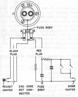
DESCRIPTION. (49) AI and BI: This fuze consists of a charging head, located in the side of the distance piece of the rocket. This charging head houses the polystryene molding housing, the plungers, and the contact wires leading to the bakelite molding. Two U-sha- ped clips, attached to the bakelite molding, secure in position the two pin plugs, one of which is red, the other black. These plugs are grooved to receive the clips. An insulated three-core cable, only two cores of which are used, leads from the black plug to the rocket ignition fuze, while a two-core cable leads from the red plug to the bomb fuze. |
|
(49) AII and BII. This fuze, sometimes found unmarked, is a pyrotechnic aerial burst fuze threading into the forward end of the rocket container. It ignites the rocket propellant after a delay of about 3 seconds after the bomb is dropped. The fuze body is threaded internally at the upper end to receive the aluminum closing cap, which is bored centrally to admit the three-core cable. Two leads of this cable pass through a rubber washer and a bakelite distance piece and are soldered to the twin terminals in the bakelite plug. The lower fuze body is screwed to the upper fuze body and houses both the aluminum holder containing the igniter into which pass the two leads from the terminals, and the delay pellet holder, which contains a powder pellet in its lowest, portion. The lower fuze body receives the powder train holder which is threaded externally to screw into the rocket propellant chamber. |
|
(49) AIII and BIII: This is an electrical impact fuze located in the base of the bomb pro-per. The fuze head consists of a gland set in a block of brown insulation. The two-core cable passes through the gland. The fuze is fitted with only one firing circuit, incorporat-ing a short delay for penetration purposes. The B plunger in the charging head, on de-pression, switches off the arming circuit. (See fig. 171.) |
|
OPERATION. On release from the aircraft, the charging head is charged. Since the head contains no condensers, the charge passes directly to the rocket ignition fuze and the bomb fuze. In the rocket ignition fuze, the igniter bridge fires the delay pellet and thence the powder train which ignites the propellant in the rocket chamber. |
|
The charge entering the bomb fuze passes through the resistance to the storage con-denser and the circuit is completed by either of two vibratory impact switches. The firing of the igniter bridge detonates the gaine and the bomb. |
|
Figure 171 – (49) B Rocket Bomb Fuze Assembly |
|
|
|
|