|
|
| GERMAN EXPLOSIVE ORDNANCE - BOMBS, BOMB FUZES, ROCKET, LAND MINES, GRENADES AND IGNITER |
| Chapter 2 |
| GERMAN FUZES |
| (57) – ELECTRICAL CHEMICAL TIME FUZE |
| DATA: |
|
Bombs Used in: No found in bombs. Enemy documents state "for use in H.E. bombs (Stabo type)." Could be used in any H.E. bomb with antidisturbance fuze. |
| Color: Dark grey; yellow paint around head. |
| Material: Aluminum. |
| Possible Actions: Long delay time, antiwithdrawal, and antirupture. |
| Principal Markings: El.A.Z. (57). |
|
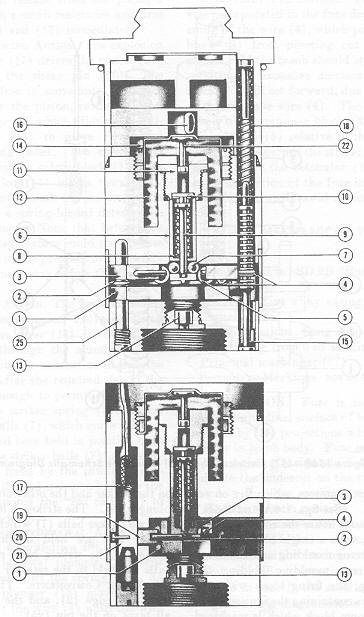
DESCRIPTION. The fuze is of type 3 construction and is fitted only with B plunger. The B plunger is connected directly through a small resistance to two igniters, which fire on release from the plane. (See fig. 156A and 156B.) |
|
Essentially four parts house the components of the fuze: The head, with a single block plunger, covering the polystyrene moulding and the firing block; the polystyrene moulding holding the plunger and wiring; the firing block with two pitch sealed chambers containing the igniter (16); and the main aluminum block which is machined to receive the following components. |
|
1. Chemically Operated Component. The solvent is contained in the chamber (12), separa-ted (in the unarmed fuze) from the plastic disc (10) by a thin aluminum disc (11). A per-forator (22) is mounted immediately above the aluminum disc. |
|
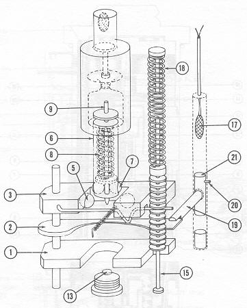
2. Striker Component. The striker body (6) is hollow. Inside is fitted the striker spring (8) under strong compression, one end of which bears on the striker and the other on the shoulder of the plunger (9). The striker is locked in position by the two striker balls (7) which project outside the striker and are held in this position by the plunger. The striker balls rest on the retainer balls (5) held in the retainer block (3). |
|
3. Block Components. The safety block (1), the knife edge (2), and the retainer block (3), all pivot on the pin (25). |
|
4. Antiwithdrawal Mechanism. The anti-withdrawal plunger (15) is under strong spring pressure from the spring (18), but is locked in place by the knife edge (2), a beveled edge of which engages in one of the grooves in the plunger. |
|
5. Arming Mechanism. The three blocks, (1), (2), and (3) are locked in position by the detent (19) which in turn is resting on the piston (21) pinned to the fuze body by the shear pin (20). |
|
Figure 156A – (57) Electrical Chemical Time Fuze |
|
|
|
OPERATION. Upon release from the plane, a charge passes through a small resistance and fires the two igniters (16) and (17) immediately. |
|
1. Mechanical Arming Action. The explosion of the vertical igniter (17) drives the piston (21) downward shearing the shear pin (20). The detent (19) is now free to move into the space formely occupied by the piston, releasing pressure on the knife edge (2) which allows the anti-withdrawal plunger (25) to move downward against the picric ring pellet. The wire (4) is held up in position by the safety block (1). On impact, the safety block (1) pivots toward the nose of the bomb from beneath the striker, and is locked in posi-tion by a spring-loaded detent. The fuze is now fully armed. Note, that before this time the chemical delay feature could not operate the detonator because of the presence of the safety block; i.e., impact is necessary before the fuze can fire. |
|
2. Chemical Time Action. The force of the explosion of the horizontal igniter (16) impinging on the solvent chamber cover (14) drives the perforator (22) down through the alumumi-num disk in (11). This permits the solvent to attack the plas-tic plug (10). After the re-quired delay, the plastic plug is soft enough to permit the plunger (9), impelled by the striker spring (8), to rise and free striker balls (7), which move inward. The striker, which had been held in position only by the pressure of the striker balls (7) on the retaining balls (5), is freed by the inward movement of the striker balls, and is driven home by the striker spring (8) against the "26" cap (13) to initiate the explosion train. |
|
3. Mechanical Antiwithdrawal Action. If any attempt is made to withdrawn the fuze after impact, the anti-withdrawal plunger (15) will move downward impelled by the spring (18). As the antiwithdrawal plunger (15) moves downward is carries with it the wire (4) until the wire is pulled from the retainer block (3). |
|
The retainer block (3) (containg the retainer balls) is now free to pivot out from under the striker, impelled by a small spring and the striker. The striker continues downward, firing the cap (13). Tests indicate that a withdrawal of only 1/16 inch or one turn of the locking ring is necessary to permit the anti-withdrawal device to work. No attempt should ever be made to withdraw this fuze. |
|
4. Antirupture Device. The antirupture device incorporated in the fuze depends on the weakening of the wire (4), which prevents the retainer block (3) from pivoting out from beneath the striker. If the bomb should strike a hard target, resulting in excessive dece-leration, the retaining block (3) will set forward, due to inertia, bending or shearing the wire (4). The movement thus allowed to the retainer block (3) displaces the retaining balls (5) relative to the striker balls (7) sufficiently to permit the striker (6) to move downward and fire the detonator (13). Also, any excessive distortion of the fuze in the bomb will operate the anti-withdrawal device. |
|
Figure 156B – (57) Electrical Chemical Time Fuze Schematic Diagram |
|
|
|
|