|
|
| GERMAN EXPLOSIVE ORDNANCE - BOMBS, BOMB FUZES, ROCKET, LAND MINES, GRENADES AND IGNITER |
| Chapter 2 |
| GERMAN FUZES |
| (66) – SPECIAL IMPACT FUZE |
| DATA: |
| Bombs Used in: SD 10 A. |
| Color: Dark plastic fuze case. Vane assembly unpainted. |
| Material: Plastic, steel, zinc, aluminum, etc. |
| Possible Actions: Instantaneous. |
| Arming Times. |
| Principal Markings: Z (66) (not visible in assembled fuze). |
| Secondary Markings: edr Z 15. |
|
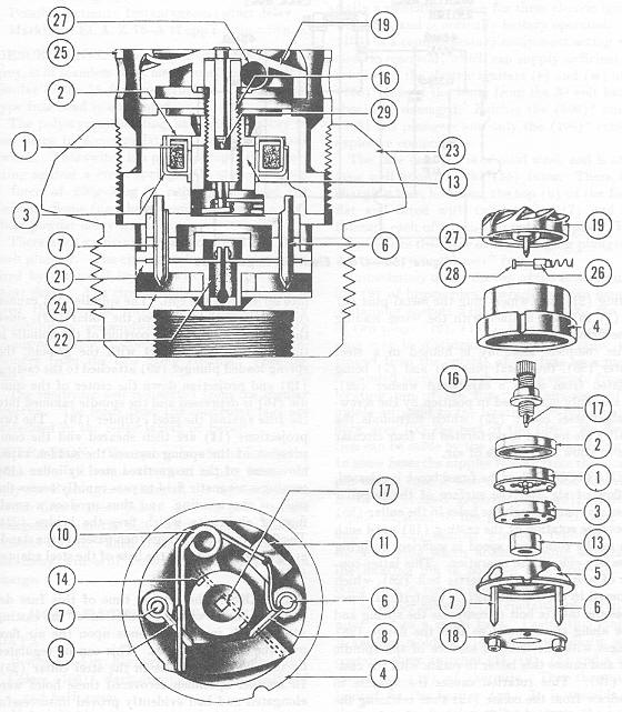
DESCRIPTION. Wound on a plastic former (1) are 54 turns of shellac insulated copper wire of 30 SWG. The mean diameter of the coil so formed is 0.75 inch. Two thicknesses of thin plastic strip are wound around the circumference of the coil to insulate the wind-ing from the two soft iron pieces (2) and (3), which enclose the three external surfaces of the coil and act as a magnetic shield against any stray external fields. (See fig. 149.) |
|
The coil assembly is housed in the black opaque plastic molding (4), and is retained in position by the transparent plastic molding (5), which is a push fit. Mounted in the mol-ding (5) are two metal pins (6) and (7) to which are attached respectively the contact projections (8) and (9). The ends of the winding of the coil are threaded through a nipple which projects from the former (1) through the soft iron piece (3). One of these ends is attached to the metal pin (6) while the other is connected to one end of the spring wire (10). A small quantity of bitumastic (11) completes the insulation. |
|
When the fuze is assembled the aluminum alloy collar (12) is retained within the molding (4) by a magnetized steel cylinder (13). This latter is a push fit within the coil assembly and is itself retained by two small projections (14) on the molding (5). Screwed down into the collar (12), which is itself prevented from rotating by a key-way (15), is an alu-minum spindle (16). When the fuze is in the unarmed condition, a projection (17), from the base of this spindle retains the spring wire (10) in the position shown dotted so that it makes contact with the projection (8) thus producing a closed circuit in the coil. The base of the molding (5) is then closed by a plastic disc (18), which is pressed into posi-tion. |
|
Mounted on the spindle (16) so that it can rotate freely is the zinc alloy casting (19) with six impeller blades on its outer surface. The casting is retained in place by the com-position washer (20), which is held by turning over the edge of the casting. |
|
The igniter unit is housed in a separate bakelite molding (21) into which plug the metal pins (6) and (7) to make contact with the wires leading to the firing bridge (22). |
|
This complete assembly is housed in a steel adapter (23), the metal pins (6) and (7) be-ing insulated from it by a cardboard washer (24). The assembly is retained in position by the screw-threaded steel collar (25) which surrounds the impeller blades and is perfora-ted by four circular holes to allow the passage of air. |
|
OPERATION. When the fuzed bomb is released, the flow of air cover the surface of the impeller blades and out through the holes in the collar (25) causes free rotation of the casting (19) until such time as the rotational speed is sufficient to bring the safety clutch into operation. This latter consists of a spring loaded inertia bolt (26), which is housed in the channel (27). Centrifugal force causes the inertia bolt to compress the spring and move along the channel so that the flange (28) engages with the knurled sur-face of the spindle (16) and causes this latter to rotate with the casting (19). This rota-tion causes the spindle to withdrawn from the collar (12) thus releasing the spring wire (10) which flies across and makes contact with the pin (9) bringing the igniter bridge into series with the coil. The spindle (16) cannot completely withdrawn from the collar (12), since the base of the threaded portion of the spindle is turned over. On impact with the ground, the spring loaded plunger (29) attached to the casting (19) and projection down the center of the spindle (16) is depressed and the spindle rammed into the fuze against the steel cylinder (13). The two projections (14) are then sheared and the compression of the spring insures the sudden rapid movement of the magnetized steel cylinder (13) causing a magnetic field to pass rapidly across the coils of the winding, and thus produce a small flow of electricaly which fires the bridge (22). The flah from this bridge then pas-ses to the standard gaine screwed into the base of the steel adapter (23). |
|
REMARKS. The arming time of this fuze depends upon the speed of rotation of the cast-ing (19), which in turn depends upon the air flow over the impeller blades. This can be regulated by the size of the holes in the steel collar (25). In another specimen recovered these holes were elongated and had evidently proved unsuccessful since a second collar with circular holes had been welded in position over the first. |
|
Figure 149 – (66) Special Impact Fuze |
|
|
|
|